61
CREW MEMBERS AND THEIR DUTIES
1. The Operator controls the placement of the mulch by moving and aiming the discharge
hose.
2. The Loader(s) anyone responsible for adding material directly into the hopper.
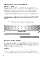
THE MATERIAL-FEED SYSTEM
The material-feed system on the Material Blower has been designed to give fast and uniform
mechanical feeding. The adjustable feeding rate and the automatic reverse control system allow
the use of varied materials while obtaining maximum production. The system is an integration of
the following four subsystems, all of which contribute to efficient material flow:
MATERIAL-HANDLING GROUP
The four major components of the material-handling group are the blower, the drag chain
conveyor or floor, the feed roll, and the airlock.
The blower is a rotary lobe, positive displacement-type unit having two double lobe impellers. It is
direct driven off the engine flywheel by a coupling. Therefore, whenever the engine is running, air
is being pumped through the system. The blower is equipped with a relief valve limiting maximum
air pressure to 12 psi (82,7 kPa), an inlet and outlet silencer for noise attenuation, and an inlet air
filter.
The drag chain conveyor receives material from the hopper and conveys it to an opening located
at the rear of the hopper where the feed roll is located. The feed roll ensures a uniform feed of
bulk material to the airlock. The feed roll is powered by a variable speed hydraulic motor. The
drag chain / conveyor is powered by a hydraulic motor that is linked in series with the feed roll
hydraulic motor.
The airlock receives the material from the drag chain conveyor and pressurized air from the
blower. Its primary function is to convey the bulk material from the atmospheric air to a sealed
chamber where the blower air stream picks it up and blows it through and out the discharge
hose. To enable the Material Blower to convey fibrous material, the airlock housing is equipped
with cutting knives and the vanes on the rotor are angled and hardened. If any material should
protrude above a vane, it will be sheared off, before the vane enters the close tolerance of the
housing by a scissor-like action between the vane and cutting knife. The rotor of the airlock is
direct-coupled to a gearbox and driven by a bi-rotational hydraulic motor.
Summary of Contents for A2548-001
Page 4: ......
Page 75: ...69 THIS PAGE LEFT BLANK INTENTIONALLY ...
Page 82: ...76 Lubrication Chart Top View of Unit 1 3 2 9 1 12 16 14 6 17 10 8 15 5 7 4 11 1 1 13 5 3 4 ...
Page 84: ...78 FINN MBH6 MATERIAL BLOWER TECHNICAL SPECIFICATIONS 166 78 31 57 67 91 97 86 ...
Page 86: ...80 NOTES 80 ...
Page 106: ...MBH6 MR1108 Rev A 100 WHEN ORDERING PARTS BE SURE TO STATE SERIAL NUMBER OF MACHINE 4 2 5 1 3 ...


