background image

43

WHEN ORDERING PARTS, BE SURE TO STATE

SERIAL NUMBER OF MACHINE

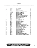
DECALS

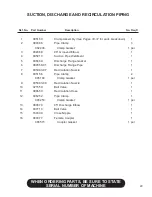
  Ref. No. 

Part Number 

Description 

  No. Req'd


011690 

FINN Nameplate 


  1


1A 

031235 

Decal "FINN" 


  2


1B 

085158 

Decal "T30 HydroSeeder" 


  2


KL2511317 

Decal "STOPPING INSTRUCTIONS" 


  1


KL2411303 

Decal "IGNITION SWITCH" 


  1


011662 

Decal "U.S. Patent Numbers" 


  1


007230 

Decal "Service Daily" 


  3


023519 

Decal "CAUTION! Wear Eye Protection..."  

  2


008097 

Decal "DANGER! Do Not Enter Tank" 


  1


085078 

Decal "Operating Instructions" 


  1


007535 

Decal "Throttle" 


  1


10 

012260 

FINN Maintain Decal Plate 


  1


11 

085137 

Decal "Pump On/Off" 


  1


12 

020976 

Decal "Patent Infringement" 


  1


13 

008286 

Decal "Agitator Speed" 


  1


14 

031331 

Decal "Gasoline" 


  1


15 

022357 

Decal "WARNING! Turn Off Engine..." 


  1


16 

012180 

Decal "To Avoid Damage To Suction Cover" 

  1


17 

011567 

Decal "DANGER! Do Not Aim..." 


  1


18 

012179 

Decal "WARNING! Do Not Operate..." 


  2


19 

006869 

Decal "Pressure Lubricator" 


  1


20 

012278 

Decal "DANGER! Hot Exhaust" 


  1


21 

012272 

Decal "Hydraulic Fluid" 


  1


22 

021665 

Decal "Hydraulic Instructions" 


  1


23 

007231 

Decal "Service Weekly" 


  2


24 

005216 

Decal "DANGER! Open Recirculation" 


  1


25 

008209 

Decal "DANGER! Before Loosening Clamp" 

  1

Summary of Contents for T30 HydroSeeder SD

Page 1: ...LBT30 SD Rev C T30 HydroSeeder Parts and Operator s Manual Model SD Serial No 9281 LeSaint Drive Fairfield Ohio 45014 Phone 513 874 2818 Fax 513 874 2914...

Page 2: ......

Page 3: ...anty 1 NOTIFY FINN CORPORATION OF THE FAILURE OF MATERIAL OR WORKMANSHIP 1 800 543 7166 Extension 246 WARRANTY FINNCORP COM 2 AFTER YOU OR YOUR SERVICE DEALER NOTIFY FINN FINN WILL VERIFY THAT WE HAVE...

Page 4: ...re 2 Secondhand used altered or rebuilt machines or parts 3 Defects malfunctions or failures resulting from accidents abuse misuse improper servicing or neglect of required opera tional guidelines and...

Page 5: ...Slurry 15 16 I General Application Techniques 15 II Application Through Hoses 15 16 Reloading 16 Cleaning and Maintenance 16 17 Hydraulic System 17 Lubrication Chart 18 Pump Maintenance 19 21 Trouble...

Page 6: ...INDEX CONTINUED Common Loose Parts Engine 38 39 Control Panel Wiring 40 Tool Kit 41 Seal Repair Kits 41 Decals 42 43...

Page 7: ...evere personal injury or death WARNING Hazards or unsafe practices which COULD result in severe per sonal injury or death CAUTION Hazards or unsafe practices which COULD result in minor per sonal inju...

Page 8: ...ximately 1050 lbs 476 kg 2 Check devices securing HydroSeeder to the truck or trailer frame 3 If the HydroSeeder is mounted to a trailer check hitch and hitch bolts safety chains lights brakes and bre...

Page 9: ...el are firmly positioned and have firm control of the hose Additional personnel to direct hose may be necessary if working on slopes The proper technique for hose holding personnel is to firmly grasp...

Page 10: ...rubber gloves and protective clothing to keep acid off skin Lead acid batteries produce flammable and explosive gas ses Keep arcs sparks flames and lighted tobacco away 7 Filling of fuel Never fill t...

Page 11: ...injury DANGE R P N 5216 B U R N H A Z A R D Contents could be under pres s ure DO NOT come in contact with material E ns ure material in line is not hot before loos ening clamps or opening valves DO...

Page 12: ...by a dual agitation process recirculation of slurry and mechanical agitation thus forming a slurry that is pumped to the discharge assembly and directed onto the seed bed by the opera tor This equipme...

Page 13: ...ely 1050 pounds 476 kg ATTACHMENTS OPTIONAL 1 Discharge hoses Discharge hoses are available in 50 ft 15 m and 100 ft 30 m lengths up to a total of 150 ft 45 m Hose of a greater length may adversely af...

Page 14: ...necessary 7 Secure the tank drain plug in the drain pipe located in the center of the bumper 8 Check to be certain pump drain plug is in place 9 Lubricate equipment See Lube Chart on page 18 A Each l...

Page 15: ...the discharge hose is the remote valve An open remote valve allows discharge of the slurry onto the area being covered WARNING Never engage turn on the slurry pump clutch when the recirculation valve...

Page 16: ...y mulch as a second operation Second at what rates usually in pounds per 1000 square feet or pounds per acre are the seeding materials to be applied Finally what are the loading capacities of the Hydr...

Page 17: ...t 400 Pounds Fertilizer per Acre x 08 Acre 32 Pounds Fertilizer per Load 345 Pounds Seed per Acre x 08 Acre 28 Pounds Seed per Load TABLE B SEED AND FERTILIzER ONLY Unit Amount of Material in Tank pou...

Page 18: ...4 8 200 757 16 40 6 23 58 4 175 662 18 25 46 4 20 75 52 7 150 568 20 5 52 1 18 5 47 125 473 23 58 4 16 40 6 100 379 25 25 64 1 13 75 34 9 75 284 27 75 70 5 11 25 28 6 50 189 30 75 78 1 8 25 21 25 95 3...

Page 19: ...arge hose or boom on the platform option into an open area away from any per sons obstructions or high voltage power lines C Open discharge and remote valves and close recirculation valve D Increase e...

Page 20: ...he tank Do not over agitate the slurry Always discharge the material with the agitator control in forward position 9 Close the hatch lid on the slurry tank NOTE If foaming occurs reduce agitator speed...

Page 21: ...tion Do NOT partially close the valve to control the distance 5 While moving along area to be seeded the operator should move the nozzle back and forth in a slow even arc 6 If application is to be int...

Page 22: ...e center of the agitator shaft with clear water B Move agitator lever to full speed to flush off inside of tank top and walls C Remove discharge nozzle and coupler gasket from the remote valve coupler...

Page 23: ...an enclosure 4 Store the HydroSeeder with all slurry valve handles in the open position To prevent damage from freezing it is advisable to remove all slurry valves and store in a heated area 5 Pour on...

Page 24: ...kly 2 6 Check Hydraulic Fluid Level HO Weekly 1 Change Hydraulic Fluid and Filter HO Seasonally 1 7 Check Fuel Tank FU Daily 1 LUBRICANT OR FLUID USED SL Seal Lube Sodium Base CL Chassis Lubricant MO...

Page 25: ...nap Ring 1 3 Impeller 1 11 Drive Hub 1 4 Mechanical Seal 1 11B Drive Hub Bolt 2 5 Pump Casing 1 11N Drive Hub Nut 2 5B Suction Cover Bolt 8 12 Clutch Retainer 1 5W Suction Cover Washer 8 12B Locking B...

Page 26: ...htening of the cap screws should be in a criss cross pattern DO NOT TIGHTEN OVER 15 LB FT 165 kg m Overtightening will crack the flange of the suction cover C CLEANING 1 To clean pump impeller 3 loose...

Page 27: ...r bolts 5B At this time check to see that the pump runs freely If the impeller rubs the cover plate either the impeller is not tight on the shaft or the cover plate needs readjustment see impeller cle...

Page 28: ...e recir culation pipe going into the tank Clear any obstructions e Replace valve assembly and slide seal back into place Lubricate outside of seal f Replace clamp 3 Obstruction in pump can be determin...

Page 29: ...n Cover O Ring bad Replace cover O Ring use grease Cover when replacing Nozzle Camlock Worn or no gasket Replace gasket Fittings PUMP Excessive wear Fertilizer with highly Change fertilizer Avoid abra...

Page 30: ...ac 100 gal 378 liters or more ing clamps Air entrainment See page 22 Low engine RPM Check throttle cable and linkage Below 3600 RPM No load See authorized engine dealer Soft water Slow agitator Too mu...

Page 31: ...lushed See pages 13 14 out prior to reloading Machine not being run at Reinstruct your operator See correct RPM during loading pages 13 14 Extension hose plugs Letting water run out If hose has to be...

Page 32: ...26 NOTES 26...

Page 33: ...T30 Hydroseeder Parts Manual Model SD...

Page 34: ...28 WHEN ORDERING PARTS BE SURE TO STATE SERIAL NUMBER OF MACHINE 1 2 3 2 4 2 14 15 16 10 6 7 12 9 5 8 8 11 13...

Page 35: ...ooved Elbow 1 4 085210 Suction Pipe Weldment 1 5 008469 Discharge Flange Gasket 1 6 080558 01 Discharge Flange Pipe 1 7 005083 07 Recirculation Nozzle 1 8 005156 Pipe Clamp 2 005183 Clamp Gasket 1 per...

Page 36: ...30 WHEN ORDERING PARTS BE SURE TO STATE SERIAL NUMBER OF MACHINE 15 5 1 3 9 8 7 13 11 12 14 10 4 6 7LW 7B 5B 5W 1N 1B 12LW 8B 8LW 2 12B 11B 11LN 16...

Page 37: ...al Lip Seal 1 7 080498 Casing Bearing 1 7B 0X0740 Bearing Bolt 4 7LW 00W07L Bearing Lock Washer 4 8 080498 Frame Bearing 1 8B 0X0728 Bearing Bolt 4 8LW 00W07L Bearing Lock Washer 4 9 080491 Pump Shaft...

Page 38: ...32 WHEN ORDERING PARTS BE SURE TO STATE SERIAL NUMBER OF MACHINE 1 2 4 25 3 6 7 10 15 16 17 17 18 18 19 20 22 11 12 13 14 8 9 23 24 5 21...

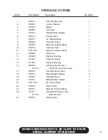
Page 39: ...er Elbow 1 10 085156 Pressure Hose 1 11 FW71451 Male 90 Adapter Elbow 1 12 022592 Street Tee 1 13 055229 Reducer Bushing 1 14 012044 Pressure Gauge 1 15 011656 Reducer Bushing 1 16 022850 4 Way Hydrau...

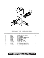
Page 40: ...d Bolt 2 2 080642 Hydraulic Pump 1 3 F30 0001 Hydraulic Pump Coupling Guard 1 4 080647 Coupling Half 5 8 Bore 1 5 080324 Coupling Insert 1 6 085023 Coupling Half 1 Bore 1 7 190123 24 1 4 Sq Key x 1 1...

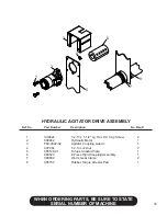
Page 41: ...escription No Req d 1 0X0824 1 2 13 x 1 1 2 Lg Hex Hd Cap Screw 2 2 080482 Hydraulic Motor 1 3 F60 0022 02 Agitator Coupling Guard 1 4 00Y08L 1 2 13 Locknut 2 5 085128 01 Torque Arrestor Plate 1 6 080...

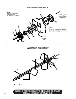
Page 42: ...1F 2 3 4 5 6 7 8 9 1 1 2 Agitator Shaft Through Back Side Outside Of Tank Wall NOTE To tighten Turn nut not bolt Torque to 25 Ft Lbs DO NOT OVER TORQUE NOTE 085161 01 Rear Bearing Assembly 085161 02 F...

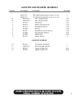
Page 43: ...g Ring 1 per 1F 085162 02 Rear Clamping Ring 1 per 2 007416 Shaft Seal 1 per 3 006975 Rubber Flangette Seal 1 per 4 007212 Flangette w Groove 1 per 5 003022 Bearing 1 per 6 007211 Flangette w Lube Cou...

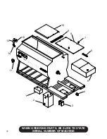
Page 44: ...38 WHEN ORDERING PARTS BE SURE TO STATE SERIAL NUMBER OF MACHINE Hydro Seeder T 30 1 2 3 4 5 6 7 8 9 10 11 12 13 14...

Page 45: ...eservoir 1 3 F30 0001 Hydraulic Pump Coupling Guard 1 4 004593 Drain Plug 1 5 085139 Fuel Tank 1 6 085132 02 Fuel Tank Lever Arm 1 031245 3 8 Snapper Pin 1 7 085152 Rubber Stud Mount 2 8 085127 Tank T...

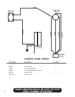
Page 46: ...RING Part Number Description No Req d 080654 Ignition Switch 1 010531 Clutch Toggle Switch 1 080526 Clutch Toggle Switch Dust Boot 1 035084 Electric Clutch 1 085128 02 Control Panel 1 IGNITION SWITCH...

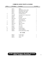
Page 47: ...g 1 080395 Narrow Ribbon Nozzle Assembly 1 004805 Narrow Ribbon Nozzle 1 080260 Nyglass Adapter 1 160750 Reducer Bushing 1 004593 Drain Plug 1 006515 Coupler Gasket 1 012681T Finn Beige Touch Up Paint...

Page 48: ...42 WHEN ORDERING PARTS BE SURE TO STATE SERIAL NUMBER OF MACHINE Hydro Seeder T30 10 1 12 4 5 14 25 24 17 9 2 13 3 11 5 19 18 16 5 6 20 21 22 15 23 7 8 18 1A 1B 6...

Page 49: ...Instructions 1 9 007535 Decal Throttle 1 10 012260 FINN Maintain Decal Plate 1 11 085137 Decal Pump On Off 1 12 020976 Decal Patent Infringement 1 13 008286 Decal Agitator Speed 1 14 031331 Decal Gaso...

Reviews:

Related manuals for T30 HydroSeeder SD