H
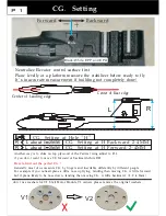
CG
Setting
.
Black White EPP and EPO
/
L
R
Center of Leading edge
Center of Rear edge
Neutralize Elevator control surface first
Plane levelly at a platform measure the stabilizer before ready to fly
P 1
Hole
Forward
Backward
-
+
CG Setting at Hole H
.
" "
L R
=
L R
=
R
L
about 1 2MM
<
-
<
-
R
L
about 1 2MM
>
-
>
-
CG Setting at H Backward 2 4MM
.
-
CG Setting at H Forward 2 4MM
.
-
Another way is to shim on top plywood of the Vertical wing adjust to R L
if you don t want to move CG forward or backward while R L
=
'
≠
It s inaccurate measurement if building not completely done
'
!
V1
V2
don t use washers for V2 T tail Motor Mounts V1 owners please remove the original washers
'
,
-
How to find out the perfect CG
?
Generally most of us measure CG by fingers and inevitable differently by different people
For example if you noticed plane a little nose up flying landing then moving CG A little forward
but if plane likely to be nose down landing then moving CG A little backward
2 0 4 0mm
,
,
.
,
.
. ( . - .
)


