MNL004_EN rev. F
Pag.
11
di
56
3.3
TRANSPORT AND HANDLING
The machine must be transported and handled solely in a vertical position and following the instructions printed on
the packaging. This precaution is necessary to avoid contamination of the compressor with oil which may cause the
rupture of valves, of the cooling coils and problems with electric motor starting.
The accessories supplied with the machine (slides, wire shelves, drawers, baskets, etc.) are shipped inside the unit. The
machine is fixed on a wooden pallet by means of screws, wrapped with polyethylene and packaged in cardboard, a
wooden crate or wooden case.
The machine must be handled using a forklift or pallet truck with suitable forks (fork length at least equal to 2/3 length
of the unit).
If the machine needs to be set down in order to bring it into the installation location, it is absolutely necessary
to wait at least 6 hours before switching it on.
The manufacturer declines any responsibility for problems due to transport carried out in any condition
different from those specified above.
3.4
POSITIONING
Incorrect positioning can cause damage to the machine and create dangerous conditions for users; therefore, the
installer must comply with the following general rules:
-
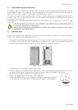
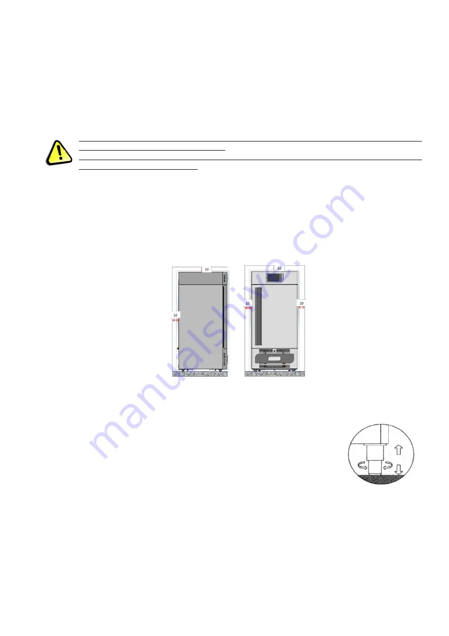
Position the machine keeping a minimum distance of 10 cm from all walls. If the machine is embedded in any type
of furniture, a correct air flow of the condensing unit (compressor/fan motors) must be always ensured. The
warranty will immediately expire, if this is not guaranteed. (Figure 1
–
equipment position)
Figure 1
–
equipment position
-
Set the machine in a sufficiently ventilated environment.
-
Place the machine far from heat sources and far from sources of electromagnetic interferences (such as motors,
generators, infrared beams, telephones) which can have negative effects on equipment functioning.
-
Avoid exposure to direct sunlight and air conditioning flows.
-
Remove the supplied accessories and the wooden pallet base.
-
Position the machine with the aid of a spirit level. If necessary, adjust the levelling feet
on the metal base (on models fitted with adjustable feet) (Figure 2
Figure 2
–
adjusting feet
Summary of Contents for 130
Page 1: ...Pag 1 di 56 ...
Page 2: ......
Page 55: ...MNL004_EN rev F Pag 55 di 56 ...
Page 56: ...MNL004_EN rev F Pag 56 di 56 MNL004_ITA rev F Via Panagulis 48 ...


