background image

MNL004_EN rev. F 


Pag. 

42

 di 

56


MODEL 100-140-280 2T 

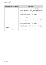
PHASE 1  

Use a Phillips head screwdriver to remove the cover (if the battery pack cover is present, do not remove the screws to 

the right and left of the terminal board or those for fixing the cover itself). 

For model 280 2T, also remove the rear electrical wiring cover channel. 

PHASE 2  

Use a vacuum cleaner or air jet to remove any dust on the condenser fins.  

Perform this procedure backwards to restore correct fastening of the rear cover. 

PHASE 3


Restore the electrical current and switch back on the device. 


MODEL 130-170-200-250-300-600 2T-400-500 ( 1T and 2T ) 


PHASE 1


Use a Phillips head screwdriver to remove the guard (3 screws). 

PHASE 2


Use a vacuum cleaner, air jet, or a long bristle brush to remove any dust on the condenser fins. 

Perform this procedure backwards to restore correct fastening of the guard. 

PHASE 3


Restore the electrical current and switch back on the device. 


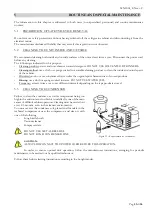
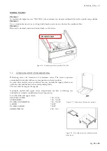
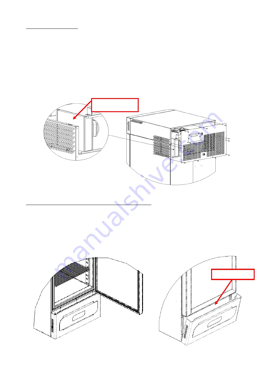
CONDENSER 


Figure 251 - Condenser position in models with lower compartment motor


CONDENSER 


Figure 24 - Condenser position in models 100-140-280


Summary of Contents for 130

Page 1: ...Pag 1 di 56 ...

Page 2: ......

Page 3: ...duct itself may be subject to change without prior notification In no event shall the manufacturer FIOCCHETTI be held responsible for any damage due to use of this manual Provide all the information required regarding operation of the device being tested in order to request technical support from FIOCCHETTI Natural gas but inflammable R290 The refrigerator contains fuel refrigerant even if permane...

Page 4: ...ATION FOR OPTIMAL USE 16 4 ECT F DISPLAY FUNCTIONING 17 4 1 CONTROL PANEL 17 4 2 ECT F CONTROL OPERATION 19 4 2 1 SWITCHING ON 19 4 2 2 How to customise the display 20 4 2 3 ECT F Menu Functions 21 4 2 3 1 Turning off the equipment 21 4 2 3 2 Changing the setpoint 21 4 2 3 3 Manual defrost function 22 4 2 3 4 Recorded alarms log 22 4 2 3 5 Language selection 23 4 2 3 6 Setting the user password 24...

Page 5: ... 40 4 3 4 1 Fault in progress warning 40 4 3 4 2 Fault ended warning 40 5 ROUTINE AND SPECIAL MAINTENANCE 41 5 1 PROHIBITION OF SAFETY DEVICE REMOVAL 41 5 2 CLEANING THE UNIT INSIDE AND OUTSIDE 41 5 3 CLEANING THE CONDENSER 41 5 4 CONDENSATE WATER DRAINING 43 6 DEMOLITION 44 7 ANNEXES 44 8 LABELLING 45 8 1 MACHINE DATA PLATE 45 8 1 1 OTHER LABELLING 46 9 CONSUMABLE MATERIALS 47 10 TROUBLESHOOTING ...

Page 6: ...d by law Repair or replacement of defective materials will occur at the manufacturer s factory where materials must be delivered with freight prepaid The manufacturer will then return them carriage forward 1 3 PURPOSE CONTENT AND RECIPIENTS OF THE MANUAL This manual has been drafted for the purpose of providing all the instructions necessary for correct use of the machine and for maintaining it in...

Page 7: ...uipment with moist or wet hands or feet Do not insert screwdrivers or other objects into the guards or moving parts Do not pull the power cord to disconnect the appliance from the electrical mains Do not allow the machine to be used by unauthorised users Before performing any cleaning or maintenance disconnect the machine from the electrical mains by switching it off and disconnecting the plug In ...

Page 8: ...n cords In explosive atmospheres or where there is a risk of fire Near to heat sources radiators etc 2 4 WARNING ON THE REFRIGERANT GAS If in the device a flammable gas is used like R290 refrigerant the following label appears on the compressor In this case some special precautions should be taken position the appliance in an environment of suitable dimensions in compliance with EN 378 the environ...

Page 9: ...fety requirements such as internal rounded corners condensate liquid drainage no rough surfaces fixed guards on moving or potentially dangerous parts and so on The maximum capacity of shelves and drawers load on all Fiocchetti models is 30 kg with weight uniformly distributed All models are for indoor use and cannot be installed outdoors Warranty will immediately expire if equipment is installed i...

Page 10: ...gs vaccines and reagents of any kind Storage of other substances or materials for general use in a non flammable or non explosive hospital laboratory or pharmaceutical environment This category includes models EMOTECA 4 C EMOTECA TWIN 4 C PLASMA VISION 15 C 20 C PLASMA VISION 2T 2 C 15 C 15 C 20 C PLASMA FREEZER 10 C 25 C PLASMA LABOR 2T 2 C 15 C 15 C 20 C PLASMA SUPERARTIC 20 C 40 C PLASMA SUPERA...

Page 11: ...ms due to transport carried out in any condition different from those specified above 3 4 POSITIONING Incorrect positioning can cause damage to the machine and create dangerous conditions for users therefore the installer must comply with the following general rules Position the machine keeping a minimum distance of 10 cm from all walls If the machine is embedded in any type of furniture a correct...

Page 12: ... Make sure that the system is suitably sized for the absorbed power of the machine It is essential to properly connect the machine to an effective grounding system set in accordance with current legislation In the event of incompatibility between the outlet and machine plug replace the outlet with a suitable type provided that the part is approved according to the laws in force If electrical cable...

Page 13: ...on of the packaging it must not show dents and or breakages Check the condition of the external frame it must not show dents and or breakages Check the condition of the power cord it should not have scratches or cuts Check that the feet and or wheels are stable Check that door opens correctly and closes hermetically Check door gaskets they should not have scratches or cuts Check that display do no...

Page 14: ...stallation Figure 6 shelves installation 3 8 2 DRAWERS INSTALLATION Insert the guides into the special slots of racks Figure 7 and pull out the telescopic guides by gently pressing on the white lever Figure 8 install them on the drawer Figure 9 and fill the drawer on the guides installed on racks Figure 10 Figure 9 installation of drawer on rack Figure 8 guides installation on drawer Figure 7 pull...

Page 15: ...ide the refrigerated compartment Observe the following instructions Do not place material over the label indicating the maximum permitted loading level if present Store material leaving a distance of at least 6 cm from sides and at least 18 cm from the top of the compartment Figure 11 12 Figure 12 Correct material storage Figure 13 INCORRECT material storage NO PO SI Figure 11 Max level label ...

Page 16: ... The units have been designed and built to work in environment with temperatures falling within the climatic class temperatures indicated on the technical data plate see Par 9 1 and at a relative humidity of 60 Do not block the motor compartment air vents Load stored material gradually at ambient temperature to grant proper refrigeration Store material on shelves or drawers Do not place products d...

Page 17: ...1 C The controller gives maximum safety in case of alarms and fault conditions signalling critical conditions and registering every event in order to help the service engineer to speed up the analysis and thus the fixing of any problems 4 1 CONTROL PANEL Figure 17 User panel interface Figure 18 DMLP Printer 9 10 5 4 3 6 7 2 1 DMLP DIGITAL MONITOR Optional ECT F CONTROL 8 STATUS OK COOL 4 3 C DMLP ...

Page 18: ...itching off glass door LIGHT timed for Medical Devices DMLP DIGITAL MONITOR 6 Alphanumeric LCD Display back lit 7 To confirm 8 To Enter and Esc from the menu 9 To increase values scroll menu 10 To decrease values scroll menu and test DMLP PRINTER 11 Feed paper 12 Paper space 13 Power Led green light when printer is fed during print out 14 Error Led red colour will blink feebly when data is transmi...

Page 19: ...s power 3 To switch on the equipment press any button for two seconds 4 When ECT F is switched on the display can be customised in four different modes using OK button see par 5 2 2 mode 1 mode 2 mode 3 mode 4 5 Once connected the equipment to the mains if DMLP Digital Monitor is installed the STAND BY string will appear Switch on the DMLP Digital Monitor pressing any button for two seconds STAND ...

Page 20: ...ompressor is OFF waiting for next cooling cycle COOL The compressor is ON to reach setpoint WAITING DEFROST After request of manual defrosting the controller waits for the necessary conditions to proceed automatically with defrosting ACCESS DENIED Attempt to access a disabled menu or after a manual defrost request if the conditions are not suitable for such action DEFROST The refrigerator defrosts...

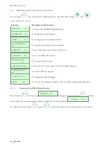
Page 21: ...o visualize recorded alarms To change strings language To set user password in order to access the menu To enter service menu functions To set date and time not present when DMLP is installed 4 2 3 1 Turning off the equipment Press the button and the string will appear Press the button to confirm At this point the controller requests further confirmation of the command To confirm press the button ...

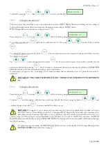
Page 22: ...ever it may sometimes be necessary to perform manual defrosting This function is enabled by following the procedure below Press the button and by using the buttons or stops at the string Confirm by pressing the button The display will show a message asking to confirm or to exit from the Menu with the message Confirm again with The controller acquires the defrosting order and the display shows the ...

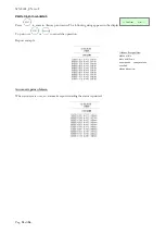
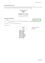
Page 23: ...e is described in the following frame Figure 20 Information on recorded alarm Pressing repeatedly the button the start date time S and the end date time of the alarm are displayed When DMLP Digital Monitor is installed all alarms will be detected by it and not by ECT F controller Failure alarms are detected in anyway by ECT F controller 4 2 3 5 Language selection Press the button and use the butto...

Page 24: ...with If entered correctly you will then be able to edit it by setting a new value and confirming with Setting the password 00 will disable password protection If the password is lost contact the manufacturer or technical support to retrieve it 4 2 3 7 Service menu Only Technical Support can enter into this menu 4 2 3 8 Setting the date and time Press the button and by using the buttons or stops at...

Page 25: ... TEMP Low temperature inside the chamber POWER FAIL HT High temperature after power failure or mains disconnection DOOR Door open alarm PROBE S1 Faulty chamber probe call Service PROBE S2 Faulty evaporator probe call Service PROBE S3 Faulty condenser probe aux call Service LOW EVAPORAT Evaporator high temperature call Service HIGH CONDENS Condenser high temperature call Service h00 m00 Clock data ...

Page 26: ...last recorded 45 days The second memory is an SD Secure Digital car a black box that grants at least five year of data storage The information stored on the SD Card is Day of the week date and hour Temperature chamber A and B probe chamber A and probe chamber B Door status chamber A and B probe chamber A and probe chamber B Door openings time chamber A and B probe chamber A and probe chamber B Rel...

Page 27: ...press any buttons for two seconds 3 When DMLP Digital Monitor is switched on the display can be customised in two different modes using OK button see par 5 3 2 mode 1 mode 2 4 3 2 DISPLAY CONFIGURATION The display can be configured in two different modes by pressing button Figure 21 DMLP display visualization modes Mode 1 Mode 2 Working status Date and time DMLP Digital Monitor must be always in S...

Page 28: ...to printer menu To access to the service menu only for Technical support To remove SD card properly To change the strings language To access to the chamber exclusion only for double temperature equipment 4 3 3 1 Turning off the DMLP Digital Monitor Press the button and the string will appear Press the button to confirm At this point the controller requests further confirmation of the command To co...

Page 29: ...th the string If there are alarms to be seen press the button to view the details of the last recorded event Use the button to scroll back to the first alarm recorded The information available is described by the following frame Figure 22 Information on recorded alarm Repeatedly press the button to view the start date time S and that of the end of the alarm ALARMS LIST m2 ALARMS LIST m2 DETECTED N...

Page 30: ... press for some seconds the button For the models equipped with the ballasted product simulation temperature probe standard only for Medical devices for single temperature models equipped with no 2 probes in the chamber Sa refers to the product temperature simulation probe whereas Sb refers to the air temperature probe 4 3 3 4 Door openings visualization Press the button then use or till the follo...

Page 31: ...tching on off limits and date time modification won t be protected anymore by password BEWARE IF THE USER PASSWORD IS LOST THERE IS NO POSSIBILITY TO RETRIEVE IT 4 3 3 6 Setting the date and time Press the button then use or till the following string Confirm and the display will blink the actual time Modify the values using the button or and confirm the new time with Continue until all the values ...

Page 32: ... It enable disable the continuous report accordingly to the pre set resolution and mode Default configuration STATUS PRINTER ON MODE TABLES MODE RESOLUTION 30 min SETTINGS WEEKLY yes DAILY yes CONTINUOUS no Printing menu Weekly report with 60 min slot Daily report selected from the menu according to the pre set mode and resolution Report of all the alarms recorded in the ALARM LIST Report of all t...

Page 33: ...setting the day using and then confirm by pressing Follow the same procedure to set the month and the year till visualizing To print use or to cancel the operation To print another day press again and repeat the above steps Report example Confirm Esc Confirm Esc Type of print Serial number of the device Report beginning and end date Automatic print Alarms list identified by Alarm code date and hou...

Page 34: ...lowing string appears in the display To print use or to cancel the operation Report example Automatic print of alarm When an alarm is over an automatic report detailing the alarm is printed Confirm Esc Alarms list specifies alarm code date and hour maximum temperature reached alarm duration ...

Page 35: ...port shows the type of alarm the maximum temperature reached and the duration of alarm Daily alarm report example PRINT LIST FAILURES Press to enter in Failures print menu The following string appears in the display To print use or to cancel the operation Report example Confirm Esc Failure list report details date and hour failure type ...

Page 36: ...rint menu The following string appears in the display To print use or to cancel the operation Report example 4 3 3 8 Service Menu Only Technical support can enter in Service menu This menu is password protected Confirm Esc Confirm Esc Parameters list report it prints DMLP Digital Monitor parameters Door openings list report details date and hour total number of door openings total duration of door...

Page 37: ...ration may take some minute it is possible To analyse data in the table To export data to a Data file for processing them with other programs e g Excel To create immediately daily temperature graphs The SD card position is identified by a sticker In the rear for models with the engine at the bottom In the upper part in the models with the motor up On the left side for models 140 and 280 2T ATTENTI...

Page 38: ...play will show Using the button or you can visualise the other probe s compartment Confirming with the button on the wished compartment a upper left b lower right the string on will start blinking Use the button or to select off then confirm The display will now show a message asking to confirm or to exit from the Menu with the message Confirm again with the button The display will show message an...

Page 39: ...y continuous sound for 4 sec Acoustic and visual simulation of the low temperature alarm Probe a Acoustic and visual simulation of the high temperature alarm Probe a Acoustic and visual simulation of the low temperature alarm Probe b if installed Acoustic and visual simulation of the high temperature alarm Probe b if installed Door micro switch integrity the display will ask to open and close the ...

Page 40: ... high temperature alarm blinking and buzzer HIGH TEMP a T Pre alarm of high temperature or high temperature alarm blinking and buzzer chamber A HIGH TEMP b T Pre alarm of high temperature or high temperature alarm blinking and buzzer chamber B LOW TEMP T Pre alarm of low temperature or low temperature alarm blinking and buzzer LOW TEMP a T Pre alarm of low temperature or low temperature alarm blin...

Page 41: ...o not use substances that can alter the organoleptic characteristics of stored products Rinsing use a cloth or sponge soaked in water DO NOT USE WATER JETS Frequency at least twice a year or at different intervals depending on the type products stored 5 3 CLEANING THE CONDENSER Failure to clean the condenser as well as temperature being too high in the environment in which it is installed is one o...

Page 42: ...ackwards to restore correct fastening of the rear cover PHASE 3 Restore the electrical current and switch back on the device MODEL 130 170 200 250 300 600 2T 400 500 1T and 2T PHASE 1 Use a Phillips head screwdriver to remove the guard 3 screws PHASE 2 Use a vacuum cleaner air jet or a long bristle brush to remove any dust on the condenser fins Perform this procedure backwards to restore correct f...

Page 43: ...ith motor compartment in lower position In some other models water is collected in a tray included in supply which is set under the unit and inserted in the corresponding slides This tray must be emptied frequently Optionally models with upper motor compartment can have a collecting tray included for automatic condensation water evaporation List of Models with upper motor EMOTECA TWIN 700 1500 SUP...

Page 44: ...n for a few days For further information about the treatment retrieval and recycling of the product please contact local officials the domestic waste collection service or the distributor Please comply with applicable laws The gas present into the system must be extracted by authorised personnel 7 ANNEXES The following documents are attached Declaration of conformity with DIRECTIVE 2006 42 EC Decl...

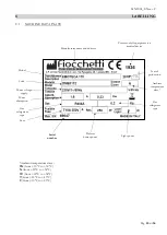
Page 45: ...dical device Year of production Model Code Ambient temperature class Power voltage supply Power absorption Gas refrigerant type Gas refrigerant type Fuse Serial number Defrost heater power Light power Ambient temperature class SN from 10 C to 32 C N from 16 C to 32 C ST from 18 C to 38 C T from 18 C to 43 C C from 10 C to 25 C ...

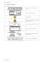
Page 46: ...re removing the guard Periodic condenser cleaning Earthing symbol Attention risk of fire only when natural refrigerants are used Glass door cleaning for Vision models Do not exceed the indicated level Substitute batteries only with DMLP Digital Monitor External dry contacts RS485 label ...

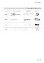
Page 47: ...stics Application Image BAT004 BATTERIA 3V Lithium Coin Cell Battery type CR 1220 ECT F Control and DMLP Digital Monitor clock battery BAT001 12V 2 1 Ah Lead battery DMLP Digital Monitor Battery BAT003 Lead battery 12V 1 2 Ah Web Light Server Battery ROT007 Thermal paper 2 pcs each package DMLP Printer ...

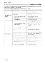
Page 48: ...o the electrical socket Control panel fault Contact Technical Support Unit does not reach the set temperature Too much material has been placed in the compartment Reduce the quantity and leave space between the shelves and walls Place products in the cabinet a few at a time after the temperature has stabilised Material was placed in the freezer area at room temperature i e 25 Store only already fr...

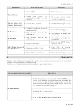
Page 49: ... Turn on the DMLP Digital Monitor par 5 3 1 Display not in STATUS OK Press OK till activating STATUS OK mode par 5 3 2 Date and time not set correctly Check date and time par 5 3 3 6 11 DIAGNOSTIC The table below lists information regarding the possible causes and actions to be taken for the most common faults which do not need automatically technical servicing Servicing on the electrical system m...

Page 50: ...al plug wait a few seconds and then re connect the plug Switch the refrigerator back on from the keyboard and once the temperature is displayed press OK so that the acoustic and visual alarms disappear Air condition the environment Check that installation has been properly performed see par 4 2 Clean the condenser see par 6 3 If the problem persists contact Technical Support ...

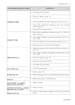
Page 51: ... If the problem persists contact Technical Support HIGH TEMP alarm Check that products have been correctly stored in the chamber see par 4 6 3 Check ambient conditions environment should be neither too hot nor too cold Clean the condenser see par 6 3 Check that door is properly closed Air condition the environment LOW TEMP alarm Contact Technical Support POWER FAIL HT Check the alarms list Check t...

Page 52: ... persists contact Technical Support PRINTER STOPPED Check that thermal paper has been properly installed Using TEST function par 5 3 3 12 check the instant battery printer voltage if voltage 11Volt wait for 24 h and run a second test if voltage is still 11 Volt replace the battery cod BAT001 If the problem persists contact Technical Support AUXIL PLANT only for Twin models Switch off the device fr...

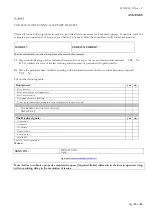
Page 53: ...ames of personnel who performed it 2 Have the problems been verified according to the information stated in the use and maintenance manual YES No Fill out the following table Equipment yes no Does not cool Does not reach the set temperature Does not switch on Equipment built into furniture Power cable connected to multiple sockets or adapters of the power outlet THE REFRIGERATOR UNIT IS NOISY DISP...

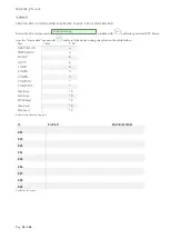
Page 54: ...5 Enter into the status data menu with and scroll the items noting the values in the table below Item Value U M KEYPAD ON n POWER ON n RESET h ECT F h COMP h COMP COMP COMP ON COMP OFF Max Evap C Min Evap C DTM Cond C Max Cond C Min Cond C Service status data for support N FAULT DATE HOUR F01 F02 F03 F04 F05 F06 F07 F08 F09 Faults list for assist SERVICE MENU m9 ...

Page 55: ...MNL004_EN rev F Pag 55 di 56 ...

Page 56: ...MNL004_EN rev F Pag 56 di 56 MNL004_ITA rev F Via Panagulis 48 ...

Reviews: