background image


START-UP AND OPERATION INSTRUCTIONS 

BIG 38/48


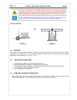
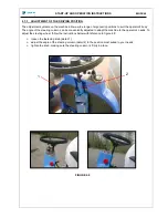
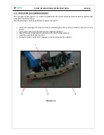
4.7.6    SQUEEGEE ADJUSTMENT 
 

To ensure perfect drying, t is essential for squeegee to be perfectly adjusted. 
This  type  of  squeegee  is  very  effective  for  drawing  the  water  towards  the  suction  hose,  but  it  needs  to  be 
perfectly parallel with the ground. To adjust the squeegee: 


  remove the key from the dashboard to avoid accidentally switching the machine on; 


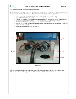
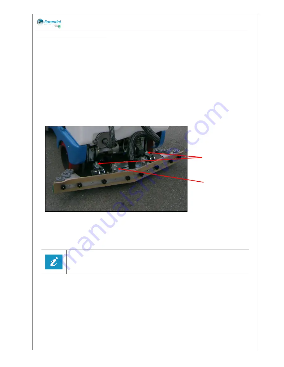
  turn the adjustment knob to adjust the angle of the squeegee (detail 1 figure 4.11). The right pressure is 

achieved when the edge of the blade touches the floor at an angle of 45° - 60° from the ground. 


  the  pressure  can  be  adjusted  by  turning  the  ring  nuts  that  adjust  the  height  of  the  squeegee  wheels 

from the floor (detail 2 figure 4.11) 


It  is  very  important  that  the  squeegee  is  adjusted  in  order  to  keep  the  squeegee  blades 
parallel and resting firmly on the floor. 

FIGURE 4.11 

Summary of Contents for BIG 38

Page 1: ...ING O FIORENTINI S p A INDUSTRIAL CLEANING MACHINES FLOOR SCRUBBER DRYER MODEL BIG 38 48 INSTRUCTIONS FOR USE AND MAINTENANCE ...

Page 2: ...ing devices 19 4 6 1 Dashboard 19 4 7 Operation 21 4 7 1 Starting and preparing the machine 21 4 7 2 Choice of detergent 21 4 7 3 Adjustment of the driving position 22 Congratulations on your choice Thank you for choosing to purchase a product by FIORENTINI S p A a global leader in the manufacture and marketing of industrial cleaning machines Our long standing experience and acquired know how are ...

Page 3: ...aintenance table 29 5 2 Battery maintenance 29 5 2 1 Measuring specific gravity 30 5 2 2 Topping up the water 30 5 2 3 Charging limits 30 5 2 4 Batteries not in continuous service or inactive 30 5 2 5 Battery disposal 30 5 3 Maintenance of the suction motor 31 5 4 Checking the electrical system 32 5 5 Inspection summary schedule 32 5 6 Maintenance Log 33 6 TECHNICAL SUPPORT 34 6 1 Contact details ...

Page 4: ...rent revision code is indicated at the bottom left corner of every page The list of revised pages is shown at the end of the manual 1 4 WARRANTY The warranty terms and conditions are stated below unless otherwise specified in the order confirmation This manual is the property of FIORENTINI S p A The reproduction of all or part of this manual or its transmission to third parties by any mechanical o...

Page 5: ...ve components must be returned to FIORENTINI S p a in order to establish the causes of any defects discovered and determine warranty applicability Repairs and replacement under warranty will be carried out on FIORENTINI s premises by third parties or on the customer s premises For services carried out on the customer premises power sources and any special equipment necessary for the repairs will h...

Page 6: ...MACHINE FEATURES AND TECHNICAL DATA BIG 38 48 ...

Page 7: ...he water and detergent As the machine travels forward the rear brush squeegee in contact with the floor collects the water which is immediately conveyed by suction to the recovery tank The dashboard regulates all the machine functions and provides the operator with an LED system that indicates the remaining battery capacity and any errors detected by the electronic board which are displayed as rap...

Page 8: ...steering assembly the driver s seat In consideration of recent EU product safety concerns FIORENTINI has designed and built this machine in compliance with the safety and health requirements provided by the applicable Directives High quality materials advanced technology and FIORENTINI s experience have been combined to produce a machine of high performance and reliability Each machine undergoes r...

Page 9: ...h 5 h Solution tank capacity 300 l 300 l Recovery tank capacity 300 l 300l GENERAL SPECIFICATIONS Traction front rear rear rear Type of traction Two electric gear motors Two electric gear motors Travel speed 0 6 km h 0 6 km h Max gradient with a full load 12 12 Depression 1600 mBar 1600 mBar Brush head pressure 0 100 kg 0 100 kg Noise operator s ear 75 dB 75 dB Minimum turning radius 2450 mm 2800 ...

Page 10: ...r vehicles modifying or tampering with the protection devices charging the batteries in locations with insufficient ventilation failure of operators to comply with current safety regulations procedures fitting equipment devices likely to interfere with machine operation introducing changes or alterations not authorised by FIORENTINI using acid solutions likely to damage the machine failure to comp...

Page 11: ...FETY AND WARNING DEVICES Tampering with safety devices and their removal or deactivation while the machine is in operation is strictly prohibited The efficiency of safety and warning devices should be regularly checked see point 5 1 Front brush guards The BIG 38 48 machine has three nylon bristle brushes that rotate during normal operation Access to hazardous areas is prevented by plastic casing t...

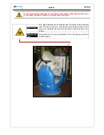
Page 12: ... risk of injury to machine operators Warning signs and indications regarding the accident prevention systems and procedures to be used have been provided for machine operators in order to minimise residual risks RISK OF CRUSHING Risk of crushing is present when replacing the front brushes when checking the brushes in the suction motor when adjusting the squeegee When replacing the brushes and adju...

Page 13: ...riangular with black pictograms on a yellow background PROHIBITIONS These signs are round with black pictograms on a white background with a red stripe What is this This sign indicates the risk of crushing by moving parts inside the machine What should I do During installation or maintenance work ensure that the ignition key has been removed from the dashboard What is this This sign prohibits the ...

Page 14: ...h these signs What is this This sign indicates risk of crushing due to closure of the recovery tank This can be tipped to one side along the longitudinal axis of the machine to facilitate cleaning of the tank and to provide access to the battery What should I do Take particular care during maintenance and if necessary provide a suitable support ...

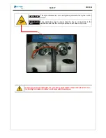
Page 15: ...t is strictly forbidden to remove or tamper with these signs What is this This sign indicates risk of crushing during maintenance by the suction motors What should I do Take particular care to ensure that the key is not inserted in the dashboard and that the motor protection cover does not tip over ...

Page 16: ...ine has not been damaged during transport and that all the material listed in the transport documentation has been received otherwise the forwarders and manufacturer should be promptly informed Unless otherwise agreed purchased goods will travel at the purchaser s own risk Handling must be performed with appropriate lifting equipment and devices as indicated in the following table Always ensure th...

Page 17: ...red in an enclosed dry location to ensure the proper preservation and efficiency of all its components Relative humidity must be below 80 and the storage temperature must be between 3 C and 45 C 4 3 UNPACKING THE MACHINE Cut the strapping with care so that it does not spring up Remove the staples on the base connecting the box to the pallet If the package is made of plywood remove the staples from...

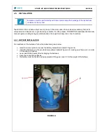
Page 18: ... conduct rigorous testing during manufacture and a thorough final inspection of each machine 4 5 1 BATTERY INSTALLATION For installation of the batteries follow the instructions given below raise the recovery tank to access the battery compartment detail 1 figure 4 4 install the battery box in the provided compartment detail 2 figure 4 4 making sure there are no cracks in the battery containers ne...

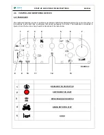
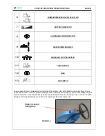
Page 19: ...eactivate the various functions of the machine Each switch has a pictogram that clearly represents its function The dashboard is illustrated in figure 4 5 and the function of each switch is described in the table below POS BUTTON FUNCTION 1 BRUSH MOTOR PROTECTOR 2 SUCTION MOTOR LIGHT 3 ROTATING BEACON SWITCH 4 BRUSH ROTATION STOP 5 HORN FIGURE 4 5 1 2 3 4 5 6 7 8 9 10 11 12 13 ...

Page 20: ... button is installed on the left side of the fairing on the BIG 38 48 floor scrubber dryer for use whenever a situation of real or presumed danger arises Pressing the emergency button immediately stops all machine functions Once the problem has been resolved and the machine is ready for use it can be restarted simply by returning the emergency button to its original position see figure 4 6 Push in...

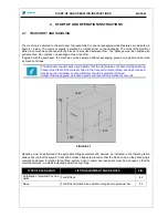
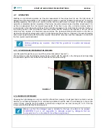
Page 21: ...viously the second cleaning action must be performed with the brushes lowered the solenoid valve open and the squeegee in contact with the floor suction switch activated Before performing any operation check that the guards are in position and properly secured 4 7 1 STARTING AND PREPARING THE MACHINE Load the water through the cap on top of the solution tank detail 1 figure 4 7 The machine can now...

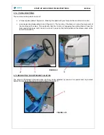
Page 22: ... angle of the steering column can be conveniently adjusted to adapt the machine to the operator s needs To adjust the steering wheel follow the instructions below with reference to figure 4 8 loosen the fastening knob detail 1 adjust the angle of the steering column detail 2 to the position most suited to your needs tighten the knob making sure the steering column is firmly in place FIGURE 4 8 1 2...

Page 23: ...s to slow the movement of the machine until it stops This pedal also has the function of engaging the parking brake Press the brake pedal fully down until it locks to unlock it press on the brake pedal and the release knob at the same time detail 3 4 7 5 REGULATING THE DETERGENT SOLUTION The amount of detergent released during washing can be adjusted by means of a special knob tap located beside t...

Page 24: ...the dashboard to avoid accidentally switching the machine on turn the adjustment knob to adjust the angle of the squeegee detail 1 figure 4 11 The right pressure is achieved when the edge of the blade touches the floor at an angle of 45 60 from the ground the pressure can be adjusted by turning the ring nuts that adjust the height of the squeegee wheels from the floor detail 2 figure 4 11 It is ve...

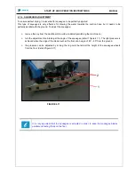
Page 25: ...r dryers have two hoses a recovery tank drain hose detail 1 figure 4 12 a suction hose detail 2 figure 4 12 To drain the water from the recovery tank position the machine over a floor drain release the tank hose detail 1 and open the rubber cap at the end of the hose FIGURE 4 12 1 2 ...

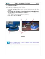
Page 26: ...h brush detail 3 figure 4 13 until the knob on the brush is accessible detail 4 figure 4 13 and press the knob to allow the brush to drop to the ground replace the brush by positioning the hexagon of the female joint on the male joint detail 5 figure 4 13 on the brush motor raise the brush vertically and rotate it until it automatically engages replace the casing and tighten the knobs Before resta...

Page 27: ... following steps should be performed to replace the blades remove the squeegee from the machine by unscrewing the nuts securing it detail 1 and place it on a bench remove the knobs fixing the blades to the squeegee detail 2 take off the steel strips detail 3 and remove the worn blades detail 4 insert the new blades and the strips tighten the knobs replace the squeegee on the machine and then adjus...

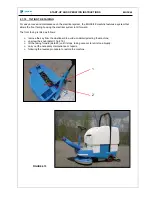
Page 28: ...ousing the electrical system to tilt forward The front fairing is tilted as follows remove the key from the dashboard to avoid accidentally starting the machine unscrew the knob detail 1 fig 4 15 tilt the fairing forward detail 2 until it stops taking care not to let it stop abruptly carry out the necessary maintenance or repairs following the reverse procedure to restore the machine 1 2 FIGURE 4 ...

Page 29: ...ng the battery water level Every 6 months Checking the condition of the brushes on each motor Checking the electrical system Checking the safety devices Once a year Carry out all checks cleaning and replacements with the machine switched off Maintenance operations should only be carried by authorised and trained personnel particularly with regard to electric and electromechanical parts Use the pro...

Page 30: ... environment temperature the batteries may be overcharged regardless of the actual temperature reached 5 2 4 BATTERIES NOT IN CONTINUOUS SERVICE OR INACTIVE Inactive batteries will lose their charge spontaneously self discharge If a period of battery inactivity is expected the following steps should be taken charge the batteries once a month with a final current intensity until considerable gas is...

Page 31: ... detail 3 and remove the plate detail 4 connecting the motors to the machine free the sponge filters beneath the motors in order to remove wash and replace them check the suction fan from the hole in the front of the suction motor to check the brushes first remove the plastic sleeve and then loosen the screws and remove the two plastic brush supports follow the reverse procedure for reinstallion O...

Page 32: ...HEDULE FREQUENCY TYPE OF TECHNICIAN CHECKS Safety devices annual professional Electrical system annual Fiorentini Braking system every 3 months professional Complete revision 2 years Fiorentini Inspection of blade condition 2 weeks operator Inspection of battery water level every 6 months operator Inspection of battery cable connections every 6 months professional Inspection of the state of the br...

Page 33: ...START UP AND OPERATION INSTRUCTIONS BIG 38 48 5 6 MAINTENANCE LOG DATE MAINTENANCE OFFICER TYPE OF SERVICE NOTES SIGNED BY ...

Page 34: ...20 Tel 0774 357184 353015 FACTORY 50030 PIANCALDOLI FI Fax 055 817144 Loc Rombola Tel 055 8173610 Many technical problems can be resolved through minor adjustments Before contacting our Technical Support service we therefore advise you to carefully read this manual If a service intervention is required clearly specify the type and details of the observed defect to help us provide the best solution...

Page 35: ... of service Machine work environment Fault Description Code of the faulty component Component name Type of fault Brief description of the fault Faulty mechanical component Faulty operation Electrical system failure Motor failure Missing component Excessive noise Water leak Other Customer remarks Please write any comments and suggestions regarding the products and services supplied by Ing O Fiorent...

Page 36: ...Date de spedition Distributed by ING O FIORENTINI S p A THE BEST IN FLOOR MACHINES BRANCHES 20132 MILAN Fax 02 2592779 Via Palmanova 211 a Tel 02 27207783 2564810 00012 Guidonia Montecelio ROME Fax 0774 353419 353314 Via B Pontecorvo 20 Tel 0774 357184 353015 FACTORY 50030 PIANCALDOLI FI Fax 055 817144 Loc Rombola Tel 055 8173610 ...

Reviews: