background image


INSTRUCTIONS FOR STARTING AND USE THE MACHINE 

I 42/60 GAS


Rev.000 

29/01/10 

25/34


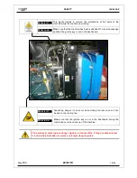
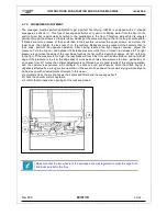
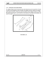
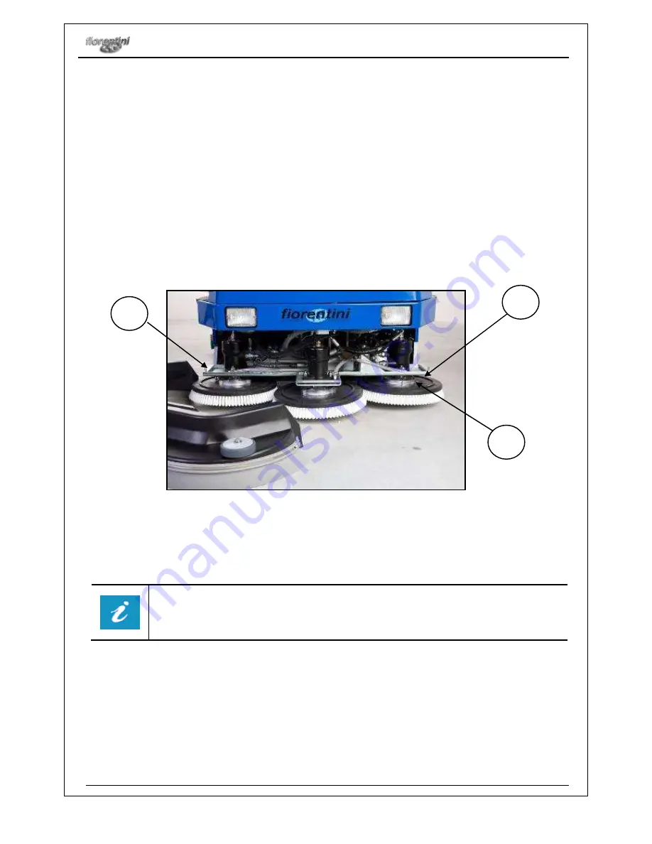
4.7.8    BRUSHES REPLACEMENT 


The operator has to follow the instructions below to replace the brushes: 
 

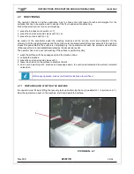
  Take the ignition key away from the dashboard in order to avoid a casual starting of the machine; 

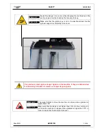
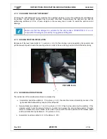
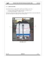
  Right side brush replacement: remove the case by means of the lever (see detail nr. 1 in picture nr. 

4.16) and translate it outside. Translate counterclockwise the right brush and remove it; 

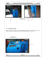
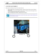
  Left  side  brush  replacement:  follow  the  same  istructions  as  for  right  side  brush  replacement  (see 

detail 2 in picture 4.18). Translate clockwise the left brush and remove it;  

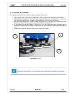
  To  set  a  new  brush  up  (see  detail  3  in  picture  4.17):  put  the  coupler  pins  under  the  brush  support 

slots, pull the brush up and translate it (clockwise for the right brush and counterclockwise for the left 
one); 

  Set again the brushes cases up and fix them by means of the lever.  


Make sure that both cases of the lateral brushes are well fixed before starting the machine. 


PICTURE N. 4.17 

Summary of Contents for I 42/60 GAS

Page 1: ...ING O FIORENTINI S R L INDUSTRIAL CLEANING MACHINES SCRUBBER MACHINE I 42 60 GAS USER MANUAL ...

Page 2: ...etergent control 4 7 6 Squeegee adjustment 4 7 7 Water discharge 4 7 8 Brushes replacement 4 7 9 Set the gas cylinders up 4 5 10 Squeegee blades replacement Congratulations for your choice FIORENTINI S r l thanking you for the preference to our product would like to remind you that FIORENTINI s S r l production covers manufacture and marketing of industrial cleaning machines and is currently a lea...

Page 3: ...5 MAINTENANCE 5 1 Periodical maintenance 5 2 Gas engine maintenance 5 3 Suction motor maintenance 5 4 Electrict equipment control 5 5 Maintenance register 6 SERVICE 6 1 Service adresses 6 2 Claim report ...

Page 4: ...n the order confirmation WARRANTY OBJECT The machine has been designed and built for a long lasting use without relevant problems Anyway if problems arise during the warranty period FIORENTINI S r l is engaged to repair or substitute for free those parts that are broken or damaged by defective materials working defects or imperfect assembly Warranty is not given for parts whose early breaking or w...

Page 5: ...s must be sent to FIORENTINI Service Dpt only after a careful analysis of the problem and its causes Following information have to be given to FIORENTINI s agent Serial number you get it from the silver label sticked on the machine 2 1 Code and position of the component taken from the spare parts list 7 2 A detailed description of the problem and its causes The components considered under warranty...

Page 6: ...GENERAL INFORMATION I 42 60 GAS Rev 000 29 01 10 6 34 ...

Page 7: ...elivery pump connected to the variable delivery pump The autoscrubber is equipped with two systems one 12V system and one 36V system The first system controls the functioning of the explosion engine i e the hydraulic solenoid valve and the gas system The second system is operated by an endothermic engine which starts a dynamo The dynamo develops a 36V voltage that controls the lift up or the sink ...

Page 8: ...age Endothermic engine Kubota 752 Squeegee suction system Three rotating brushes Water recovery system one idle wheel two traction wheels operated by two hydraulic motors steering wheel driving seat FIORENTINI Co taking the new CE safety rules into consideration manufactures the machine following the CE directives about safety and health The materials high quality the high technology and FIORENTIN...

Page 9: ...A 1150 mm 1450 mm SQUEEGEE WIDTH 1470 mm 1650 mm SOLUTION TANK CAPACITY 340 mm 340 mm RECOVERY TANK CAPACITY 340 mm 340 mm BRUSHES PRESSURE 0 120 Kg 0 120 Kg ENGINES FEATURES ENGINE Kubota 752 Kubota 752 CYLINDERS 2 2 DISPLACEMENT 750 cc 750 cc POWER 19 cv 19 cv BRUSHES HYDRAULIC ENGINE OR 80 OR 80 TRACTION HYDRAULIC ENGINE OP 160 OP 160 VARIABLE DELIVERY PUMP 14 l 14 l FIXED DELIVERY PUMP 4 2 l 4...

Page 10: ...faces with inflammable products The machine cannot be used as a means of transport for people or other means of transport The machine protection devices cannot be modified or tampered Batteries must be recharged in a fanned room The operator have always to respect safety rules The operator cannot use equipments or devices that can create problems to the machine working The machine components canno...

Page 11: ...EVICES It is absolutely forbidden to tamper or disconnect safety and warning devices while the machine is working It is important to check periodically safety and warning devices see 5 1 Side brushes protection I 42 60 GAS is equipped with three nylon brushes which rotate while the machine in on duty La macchina I 42 60 GAS e dotata di tre spazzole con setole in nylon che sono in rotazione durante...

Page 12: ...the recovery tank prevent dangers to the operator see 3 7 BURNING DANGER This kind of danger can occur during the check up of the oil engine Whilst changing or checking the oil engine make sure that the machine has been switched off a few minutes ago before opening the rear case in order to avoid to touch hot parts of the machine Special labels sticked on the case of the steering column prevent da...

Page 13: ... temper danger signals What is it Crushing danger it can be due to parts in movement of the machine What to do During the installation or the maintenance make sure that the ignition key is not in the dashboard before removing the mobile protections What is it This signal forbids to remove the protection of pieces in movement What to do During the installation or the maintenance make sure that the ...

Page 14: ... while closing the rear case or it can be due to the cooling fan What to do Make sure that the ignition key is not in the dashboard during the maintenance or the check up of the machine What is it This signal forbids to remove the protections of hot parts of the machine while the machine is working What to do Make sure that the machine has been switched off a few minutes ago and that the ignition ...

Page 15: ... the suction engine or while checking the recovery tank up What to do Make sure that the ignition key is not in the dashboard and that the cylinder support is completely turned over What is it The signal forbids to drive the machine on slopes whose gradient is higher than 13 What to do Make sure that the slope is not higher than 10 On the contrary do not drive the machine on slopes whose gradient ...

Page 16: ...rs are on the machine Otherwise the purchaser must immediately contact FIORENTINI in order to sort out the problem The purchaser is responsible for the transport of the machine if not differently agreed with FIORENTINI The machine must be handled with proper devices as stated in the scheme below Please make sure that the black arrow on the package is always in the middle of the elevator forks or t...

Page 17: ...e straps paying attention to the back spring Remove the staples that join the paperboard and the pallet If the package is mad of plywood please remove the staples from each side Cut the straps that fix the machine Lay the machine on the floor 4 4 HOW TO HANDLE THE UNPACKED MACHINE Check the machine and install the batteries if not already installed For a brief transport of the machine please disco...

Page 18: ...Hydraulic oil level Engine oil level Engine cooling water level Wheels brake Pilot lights functioning If the result of the test is positive the machine can be started On the contrary please contact immediately FIORENTINI service The test above must be periodically done in order to keep the machine always efficient The machine must be started by authorized personnel 4 6 CONTROL DEVICES 4 6 1 DASHBO...

Page 19: ...se 17 Accessory sweeping group 5 Controls alimentation fuse 18 Blinking switch 6 Direction signals and stop fuse 19 Light switch 7 Empty 20 Squeegee up and down 8 Empty 21 Vacuum motor switch 9 Empty 22 Brush up down and on off 10 Empty 23 Diesel motor temperature indicator 11 Empty 24 Key switch 12 Hour counter manometer 25 Igniter plug switch 13 Oil pressure indicator 26 Battery charger indicato...

Page 20: ...ves this pedal Before the surface is completely dry the operator must switch the solution solenoid valve off because this is not activated disactivated by the accelerator pedal The operator has to do a second washing if the surface is particularly dirty 1 wash the surface with the squeegee up and the brushes down 2 activate the brushes 3 press the solution solenoid valve switch 4 leave the solutio...

Page 21: ...e detail nr 1 in picture nr 4 8 for the steering column regulation the operator can pull backward or push onward the steering wheel in order to have a driving position which fits his her body 4 7 4 RUDDER BAR FUNCTIONING The rudder bar of this scrubber machine is composed by Accelerator pedal see detail nr 3 in picture nr 4 9 the machine moves forward by means of the right pedal and backwards by m...

Page 22: ...01 10 22 34 4 7 5 DETERGENT CONTROL During the washing the operator can control the detergent quantity by means of a cock which is at the bottom of the machine on the left inside the protection rubber see detail nr 1 in picture 4 10 PICTURE N 4 10 PICTURE N 4 9 4 2 1 3 1 ...

Page 23: ...n it to increase pressure to the floor or loosen to decrease it The right pressure is got when the edge of the rear blade touches the floor with a slanting of approx 60 45 r eferring to the floor If the pressure is too high the rear blade will touch the floor with its side surface and not with its edge If the pressure is too low the edge doesn t work well and lets some water on the floor particula...

Page 24: ...s for water discharge picture 4 15 A pipe for the recovery tank discharge see detail nr 1 in picture nr 4 15 A suction pipe see detail nr 1 in picture nr 4 15 If you need to discharge water from the tanks you have to place the machine on a dump well release the pipe of the tank and open the rubber cap at the end of the pipe itself PICTURE N 4 15 1 2 ...

Page 25: ...anslate counterclockwise the right brush and remove it Left side brush replacement follow the same istructions as for right side brush replacement see detail 2 in picture 4 18 Translate clockwise the left brush and remove it To set a new brush up see detail 3 in picture 4 17 put the coupler pins under the brush support slots pull the brush up and translate it clockwise for the right brush and coun...

Page 26: ...in picture 4 18 and fix it by means of belts see picture 4 18 Insert the pipe into the cylinder and tighten it with a clamp Insert the other end of the pipe into the machine through the hole see detail nr 2 in picture 4 18 Insert the rubber pipe joined to the copper pipe into the machine Before starting the machine again make sure that the gas cylinder has been perfectly set up and that there are ...

Page 27: ...ueegee should be removed from the machine To do that lift the squeegee support in UP position then remove the suction pipe from the squeegee partially unscrew the screws At this point remove the squeegee from the machine and place it on a desk Now remove the screws both on the front part and on the rear part of the squeegee the steel straps and the three worn rubber blades as well Perform the inve...

Page 28: ...of the clean water tank Every month Check and regulate the breaking system Replace the motor oil filter Check the belts tension Every three months Check the connection of the battery cables Check the water battery level Replace the air filter Replace the hydraulic oil filter Every six months Cleaning Controls Replacement Check the coal brushes of each motor Check the pipes of the hydraulic system ...

Page 29: ...TENANCE The vacuum motors must be checked and cleaned The brushes should be checked all six months and replaced if necessary After removing the key from the dashboard remove the motor cover located on the rear part of the machine To release the motors fig unhook the hooks fig and detach the plug fig In this way it is possible to extract the motors and release the sponge filter under the motors tha...

Page 30: ... check the electric system up every two years Disconnected cables or burnt cables must be immediately replaced Interventions on the electric system must be carried out by a trained technician Every kind of intervention not explained in the operator manual must be carried out by FIORENTINIs technicians ...

Page 31: ...MAINTENANCE I42 60 GAS Rev 000 29 01 10 31 34 5 5 MAINTENANCE REGISTER DATE OPERATOR INTERVENTION SIGNATURE ...

Page 32: ...ical problems can be sorted out with short intervention This is why FIORENTINI S r l suggest to read carefully this manual before using the machine On the contrary if the customer needs a FIORENTINI S technician please inform us about the problem in order to sort it out with the right material 6 2 CLAIM REPORT Please fill in the format below if the machine shows particular problems ...

Page 33: ...Machine CUCCIOLO Type Purchase date S N Warranty YES NO Work hours Where does the machine normally work Fault Code of the defected component Description Fault Fault short description Mechanical component Wrong functioning Electric system Engine Missing component Estremely noisy Water leak Other Customer s suggestion ...

Page 34: ...____________________ Date de spedition ING O FIORENTINI s r l THE BEST IN FLOOR MACHINES FILIALI 20132 MILANO Fax 02 2592779 Via Palmanova 211 a Tel 02 27207783 2564810 00155 ROMA Fax 06 22754075 Via Carlo Carrà 13 Tel 06 22754040 2275060 STABILIMENTO 50030 PIANCALDOLI FI Fax 055 817144 Loc Rombola Tel 055 8173610 Distributed by ...

Reviews: