159
6
OPTIONAL EQUIPMENT
id.:
DB 260 REV. 00 02/07/2015
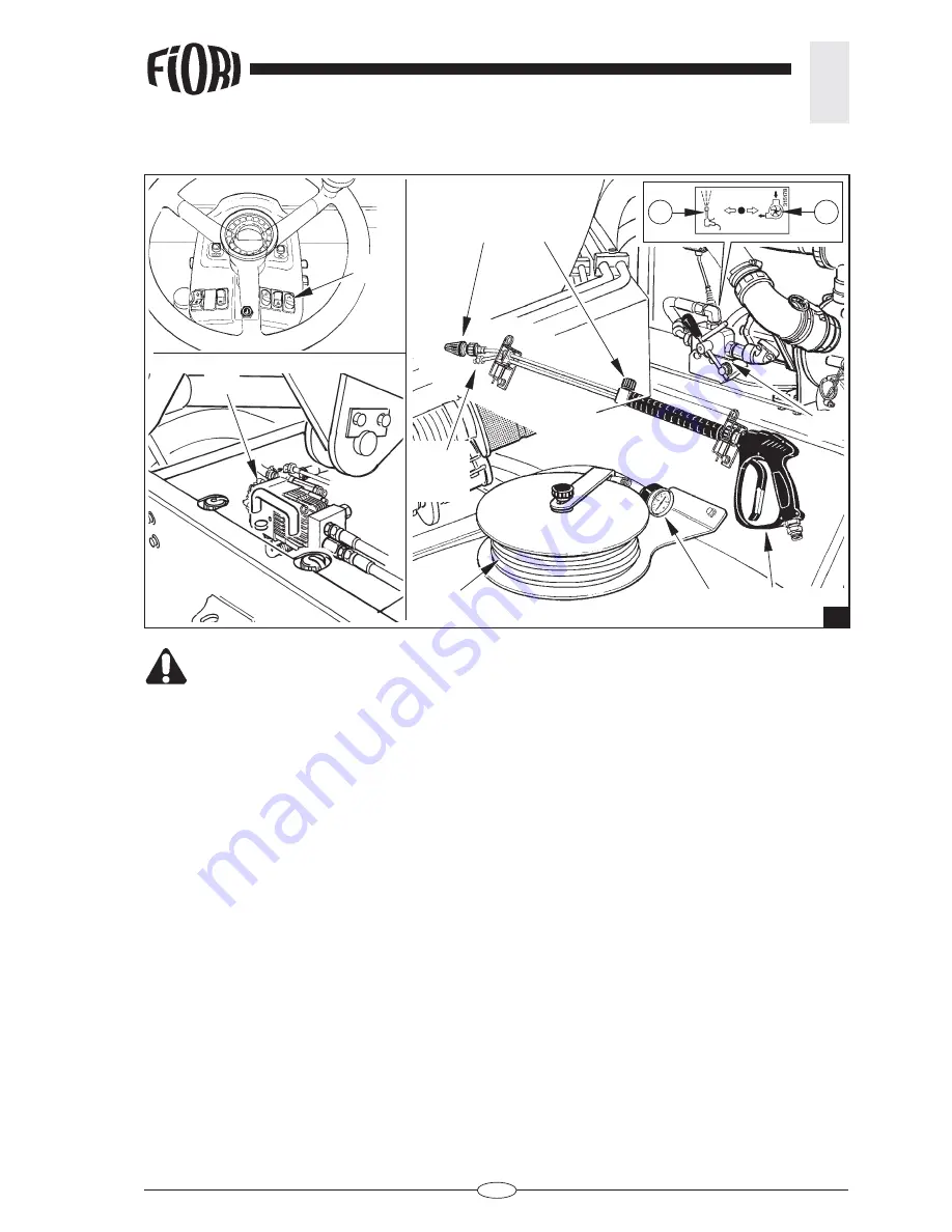
6.2.4 USING THE POWER JET CLEANER
(fi g. 3)
The high energy of the pressurised jet may be extremely dangerous. Keep away
from persons, animals and any delicate object when the pump is operating.
Never direct the pressurised jet at persons, animals, electrical equipment and fragile
parts in general. Never put your hands in the pressurised jet (RISK OF INJURY).
Never leave the hose F under pressure. This may cause damage to persons or
things should you involuntarily pull the trigger of the power jet cleaner.
CAUTION: Wear protective goggles and clothing during use of the power jet cleaner.
Always hold the power jet cleaner with both hands when it is operating.
- Start the engine and engage the parking brake.
- Press the switch
S
on the dashboard in the cabin to activate the water pump circuit.
- Turn the lever of the switch
E
to position (
2
) to activate the power jet cleaner pump
H
.
- Open the catches and extract the power jet cleaner
A
, unwind the high-pressure hose
F
from its reel and
screw it onto the power jet cleaner.
- Turn the valve
D
on the power jet cleaner until the low-pressure nozzle
B
is completely open.
- Hold the trigger of the power jet cleaner pulled and let the pump run until all the air has been expelled from
the tubes and the water fl ows uniformly and continuously from the nozzles
B
and
C
.
- Gradually close the valve
D
on the power jet cleaner until the pointer of the water pressure gauge
G
indicates
that the operating pressure has been reached (150 bar).
- Close and open the power jet cleaner two or three times to check proper functioning. Releasing the trigger,
the pump must stop and restart as soon as the trigger is pulled again; the pressure gauge reading must drop
by 10-15 bar to return to the set value.
- When you have fi nished work, fully open the low-pressure nozzle
B
of the power jet cleaner.
- Turn the lever of the switch
E
to position (
1
) to close the oil inlet to the pump
H
.
DANGER:
3
D
C
B
F
G
A
H
1
2
E
S
Summary of Contents for DB 260
Page 2: ......
Page 4: ......
Page 6: ......
Page 22: ......
Page 48: ...48 3 SAFETY PRECAUTIONS id DB 260 REV 00 01 07 2015 VEHICLE EXTERIOR ...
Page 110: ......
Page 166: ...166 TECHNICAL ANNEXES DB 260 REV 00 01 07 2015 id HYDRAULIC DIAGRAM ...
Page 168: ......
Page 174: ......
Page 175: ...2013 04 08 00 02 0796 Catalog Section 78 PowerView Model PV101 C User s Guide Version3 2 ...
Page 176: ......
Page 183: ...00 02 0796 3 2013 04 08 Faceplate Features ...
Page 221: ...00 02 0796 41 2013 04 08 NOTES ...
Page 222: ...NOTES ...
Page 223: ...NOTES ...
Page 226: ...www fwmurphy com PV101 ...


