15465 Rev F 5/2/97 P/N 15465:F
25
3.0 Installation
Mounting Options
The cabinet may be either semi-flush or surface mounted. The cover is
removable during the installation period.
The cabinet mounts using two key
slots and two additional 0.250"
diameter holes located in the
backbox. The key slots are located
at the top of the backbox and the two
securing holes at the bottom. Refer
to Figure 3.2-1 for cabinet
dimensions.
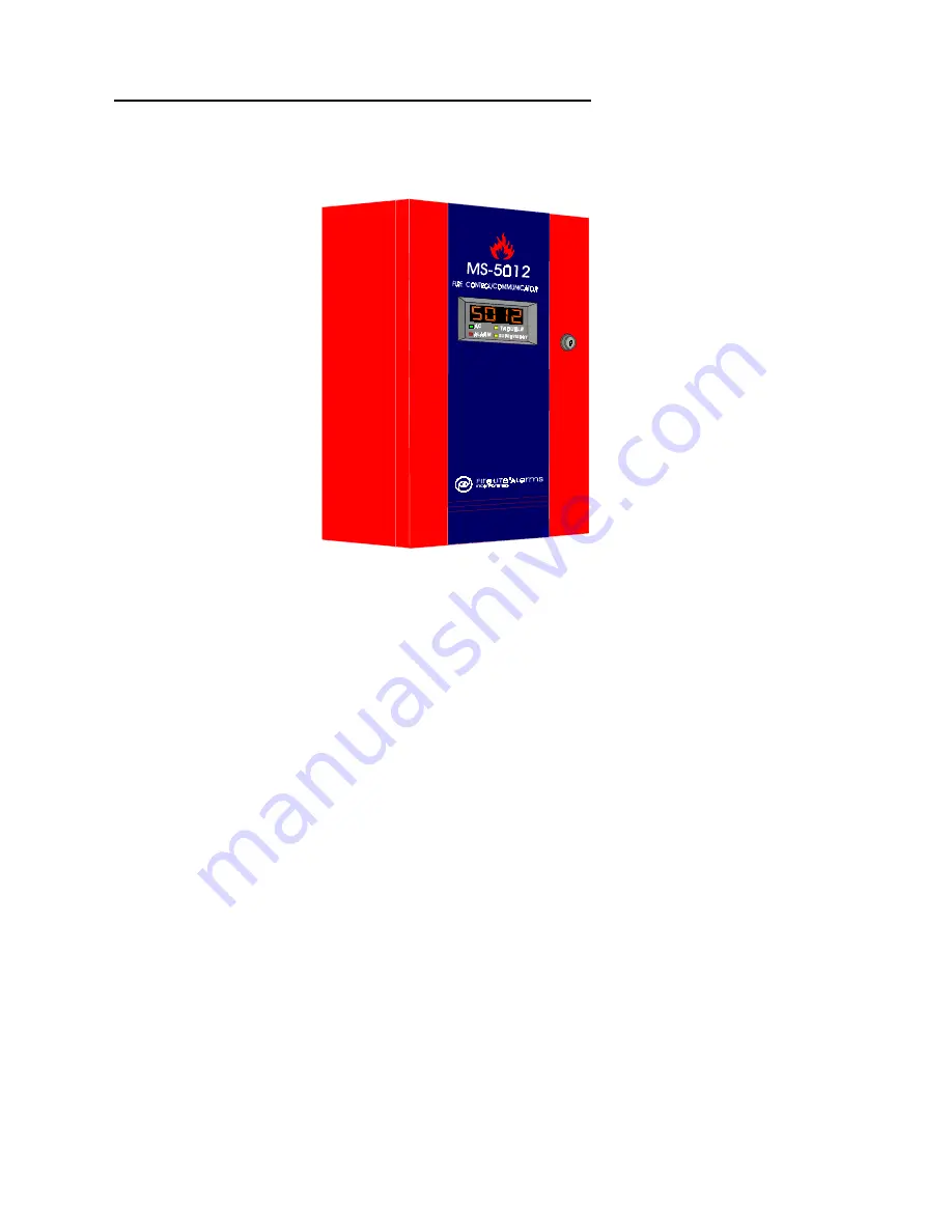
3.1 Cabinet
Figure 3.1-1:
The MS-5012
The MS-5012 has five zone input circuits. The maximum loop resistance
limit for each is 100 ohms. All field wiring of each zone is supervised for
opens and ground faults. Both conditions are visually and audibly
annunciated as well as communicated to a Central Station.
Zone 1 is a Style B Initiating Device Circuit (IDC) designed to accept any
N.O. contact device on TB2, terminals 1-2. It is power limited to 2.66 mA
(standby) and 4.46 mA in alarm. Factory Default is “Pull Station.” Refer to
Section 4.0: Programming.
Zone 2 is a Style B Initiating Device Circuit designed to accept any N.O.
contact device and conventional 2-wire, 12-volt smoke detectors on TB2,
terminals 3-4. It's power limited to 7.17 mA in standby and 24 mA in
alarm. For a list of compatible 2-wire detectors refer to Fire-Lite
Compatibility Document. Factory Default is “2-wire Detectors.” Refer to
Section 4.0 Programming.
Zone 3 is a Style D Initiating Device Circuit. It is designed to accept: N.O.
contact devices, 2-wire smoke detectors and Waterflow sensing devices on
TB2, terminals 5-8. It's power limited to 7.17 mA in standby and 24 mA in
Alarm. A maximum of five waterflow devices may be used per NFPA 71.
For a list of compatible 2-wire detectors refer to Fire-Lite Compatibility
Document. Factory Default is "Waterflow." Refer to Section 4.0
Programming.
3.2 Input Circuits
Technical Manuals Online! - http://www.tech-man.com
firealarmresources.com

