15465 Rev F 5/2/97 P/N 15465:F
33
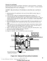
MS-5012 Backbox
MS-5012 Main Circuit Board
Optional AC Terminal Block
An optional AC terminal block is available for the MS-5012 Control Communicator. The terminal
block can only be used on the newer, larger (14.5" x 12.5" x 2.875") backbox. It cannot be installed
in the older, smaller (12.0" x 9.0" x 2.75") backbox.
CAUTION! Make certain all power (AC and battery) is removed before any connections are
made.
1. Mount the optional AC terminal block to the lower left of the MS-5012 backbox using two
supplied screws.
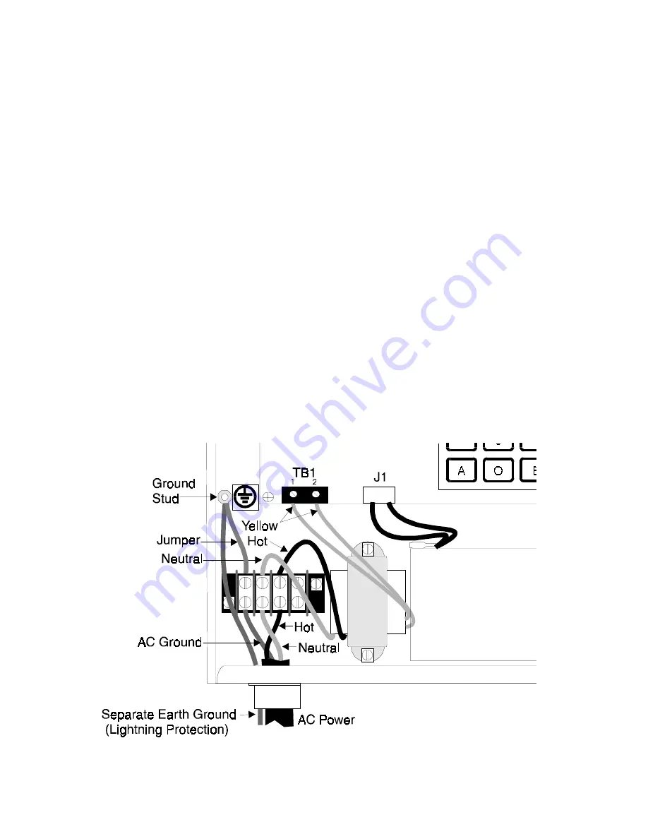
2. Connect AC power wiring to the optional terminal block as shown in Figure 3.6-2.
3. Connect the black and white wires (primary) from the MS-5012 system transformer to the
optional terminal block as illustrated below. Make certain the black AC wire (Hot) is connected
opposite the black transformer wire and the white AC wire (Neutral) is connected opposite the
white transformer wire.
4. Make certain that the yellow wires (secondary) from the MS-5012 system transformer are con-
nected to Terminal Block TB1 located in the lower left corner of the MS-5012 main circuit
board.
5. Install a jumper between the terminal block and the backbox ground stud as illustrated below.
This will be used to provide lightning protection to the panel. (Make certain the jumper is
connected opposite the green AC ground wire on the terminal block).
6. Install a solid earth ground connection to the backbox ground stud as illustrated below. This
will be used to provide lightning protection to the panel.
7. Press the AC terminal cover firmly into place.
8. Reapply AC and battery power to the MS-5012 Control Communicator.
Figure 3.6-2: Optional AC Terminal Block Installation
Technical Manuals Online! - http://www.tech-man.com
firealarmresources.com


