ECC-FFT Instruction Manual —
P/N LS10031-000FL-E:B 9/4/2013
13
Installing the ECC-FFT
Installation
2.3 Installing the ECC-FFT
2.3.1 Operating Power
Connect the ECC-FFT to the appropriate DC power source. See Section 1.3 for compatible equip-
ment and Section 1.5 for power requirements.
2.3.2 DIP switch settings on ECC-FFT
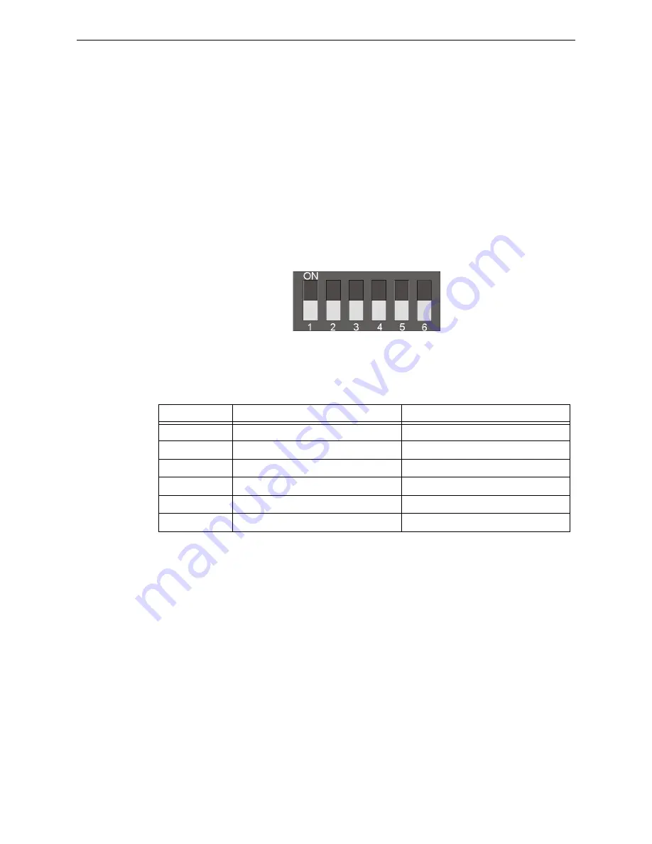
Use the on-board DIP switch to assign the configuration setting to the ECC-FFT.
1. Refer to Figure 2.3 for location of the DIP switches on the ECC-FFT board.
2. Configure the ECC-FFT using the dip switch settings in Table 2.1. Add SLC modules to the
system through Autoprogram feature. See Section 3.3 for Autoprogram Operation.
DIP Switch
DIP Switch
ON
OFF
1
SLC Devices Installed
SLC Devices not Installed
2
Trouble Piezo Enabled
Trouble Piezo Disabled
3
SLC Class A Supervision
SLC Class B Supervision
4
Phone Circuit Class A Supervision
Phone Circuit Class B Supervision
5
Not Used
Leave in OFF position
6
Not Used
Leave in OFF position
Table 2.1 ECC-FFT DIP Switch Configurations
Figure 2.3 DIP Switch


