background image

S2000  15017 Rev H  10/08/96   P/N   15017:H

46

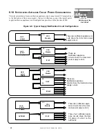
Figure 6-6:  Typical Supply/Notification Circuit Configurations

CPU

Module

J5

CPU

Module

J5

J6

J5

IC-4F

CPU

Module

J5

AVPS-24F

IC-4F

J5

CPU

Module

IC-4F

ICE-4F

J5

J6

J5

J6

J5

Bottom view of the

IC-4F/ICE-4F

main
power
supply

main
power
supply

main
power
supply

main
power
supply

These two notification appli-
ance circuits share the total
main power supply current.

These four notification appli-
ance circuits share the total
3.0 amps of current on the
AVPS-24F.

These six
Notification appliance
circuits share the total main
power supply current.

6.10 N

OTIFICATION

 A

PPLIANCE

 C

IRCUIT

 P

OWER

 C

ONFIGURATIONS

The total current drawn from a notification appliance circuit cannot exceed 3.0 amps (subject

to the limitations of the power supply).  Figure 6-6 illustrates some of the typical power

supply/notification appliance circuit configurations possible with the Sensiscan 2000.

These two notification appliance cir-
cuits share the total main power
supply current.

These ten
Notification appliance
circuits share the total main power
supply current.

Summary of Contents for SENSISCAN 2000

Page 1: ...12 Clintonville Road Northford CT 06472 H P N 15017 H ECN 96 200 Document 15017 10 8 96 Rev THE SENSISCAN 2000 INSTALLATION OPERATION AND PROGRAMMING MANUAL ...

Page 2: ...d yourself with a proper wrist strap before handling any circuits so that static charges are removed from the body Use static suppressive packaging to protect electronic assemblies removed from the unit Follow the instructions in the installation operating and programming manuals These instructions must be followed to avoid damage to the control panel and associated equipment FACP operation and re...

Page 3: ...eld Wiring of the CR 4F and the CRE 4F 28 SECTION FIVE THE POWER SUPPLIES 29 The MPS 24AF MPS 24AFE Main Power Supply 30 The MPS 24BF MPS 24BFE Main Power Supply 33 Field Wiring of the Optional Audio Visual Power Supplies 36 The R45 24 R45 24E Remote Battery Charger 37 SECTION SIX APPLICATIONS 38 Waterflow Alarm 38 Supervisory Service 38 Central Station 38 Digital Alarm Communicator Transmitters D...

Page 4: ...nded using one or more of the following optional modules or boards System expansion must comply with The physical limitations of the cabinet configuration The electrical limitations of the system power supplies see Appendix A The capacity of the standby batteries see Appendix A 1 2 KEY FEATURES Distributed microprocessor electronics Field programmable in nonvolatile memory Alarm and trouble resoun...

Page 5: ...BORATORIES DOCUMENTS UL 38 Manually Actuated Signaling Boxes UL 217 Smoke Detectors Single and Multiple Station UL 228 Door Closers Holders for Fire Protective Signaling Systems UL 268 Smoke Detectors for Fire Protective Signaling Systems UL 268A Smoke Detectors for Duct Applications UL 346 Waterflow Indicators for Fire Protective Signaling Systems UL 464 Audible Signaling Appliances UL 521 Heat D...

Page 6: ... In addition the following equipment is required for the specific NFPA standards listed below An NFPA 72 1993 Proprietary Protected Premises Control Unit requires Potter Electronic Signal Co Transmitter Model EFT C with transformer Model ULT Stock Number 1000391 An NFPA 72 1993 Central Station Protected Premises Control Unit requires UDACT F 911A Digital Communicator or an Ademco No 678 UL F Digit...

Page 7: ...n power supply initiating modules notification modules and control relay modules See Section One for minimum system requirements This installation manual covers a basic system For information on other devices refer to the installation manuals of the following products The AFM Annunciator Fixed Module Document 15970 The AFM 16ATF Annunciator Fixed Module Document 15210 The AFM X Series Annunciator ...

Page 8: ...ed from this module via the use of the Programming Key Slide in labels for programming control and system operation are provided with the CPU as well as end of line and dummy load resistors VP 1F Vented Dress Panel Covers the top row of modules in the cabinet Power Harness 71086 First Row Ribbon Cable 71087 Main Bell Power Harness 71093 KEY ___ PWD ___ Programming Key PKB Dummy Load Resistor 4 7K ...

Page 9: ... a variety of standard UL listed 24 VDC notifica tion appliances see Document 15384 for a complete list Up to 200mA of resettable power is available for four wire smoke detectors The MPS 24BF contains an integral battery charger capable of charging batteries in the 6 5 to 17 AH range Includes two sets of battery cables one with 1 4 lug type con nectors for larger batteries and one set with 3 16 lu...

Page 10: ...iating device cir cuits Circuits are power lim ited and user programmable for standard fire Waterflow Alarm or Supervisory service Also provided are four end of line and four dummy load resistors Note This module will not sup port an IZE AF Expander Dummy Load Resistor 4 7K 1 2 watt 71245 End of Line Resistor ELR 4 7K 1 2 watt 71252 RS 1459 MODULE The RS 1459 module is used in conjunction with the...

Page 11: ... The UDACT F is capable of reporting 198 points or 56 zones when used with the MS 9200 and 56 zones when used with the Sensiscan 2000 IC 4F INDICATING CIR CUIT MODULE Provides four notification appliance circuits for Style Y or Style Z opera tion Maximum signaling current is 3 0 amps 3 amps max per circuit Circuits are field programmable to respond to a single initiating zone a group of zones or a...

Page 12: ... by an AFM 16ATX to a maximum of 64 system points AFM 32AX The AFM 32AX Annunciator Control Module contains 32 red alarm LEDs a System Trouble LED an ON LINE POWER LED and a local piezo sounder with a silence acknowledge switch for au dible indication of alarm and trouble conditions at each annunciator The AEM 32ATF Expander Module expands the AFM 32AX by 32 system points One expander module can b...

Page 13: ...NETS The CAB A3F and CAB B3F cabinet assemblies consist of a backbox and a locking door with two keys The backbox and door can be ordered separately or as a complete package TR A3R TR B3R TRIM RING For semi flush mounting of the cabinet CAB B3F CAB A3F ...

Page 14: ...or conflict with the power supply and batteries may result Main Power Supply Mount the main power supply to the cabinet as illustrated in Figure 3 3 Do not wire anything at this time Chassis Mount all chassis Refer to Figure 3 2 for installation of the CHS 4 chassis Audio Visual Supplies If any optional audio visual power supplies are to be employed mount them to the chassis Refer to Figure 3 4 fo...

Page 15: ... connect the batteries at this time To silence the audible trouble sounder push the ACKNOWLEDGE switch on the CPU The system should reflect the following status On the CPU Green AC POWER indicator should be on The BATTERY FAIL indicator will be on due to the absence of batteries SYSTEM TROUBLE and POWER FAILURE indicators should be on due to the absence of batteries MODULE FAILURE indicator may li...

Page 16: ...ALL THE AVPS Install any optional AVPS 24F AVPS 24FE over the screw mounts on the CHS 4 and secure with the two provided nuts FIGURE 3 2 INSTALL A CHS 4 Install a CHS 4 in each row of the cabinet that will em ploy Sensiscan 2000 modules For proper grounding of the modules to the cabinet connect a grounding cable to one of the chassis mounting screws as illustrated FIGURE 3 1 MOUNT THE CABINET BACK...

Page 17: ...e upper end of the module into the cabinet and secure with two module screws Straighten LEDs so that they extend from the board at a 90 degree angle Step 2 Insert the pins on the expander board into the connector on the module and press the two boards together ensuring that the pins are properly aligned Step 1 Attach four standoffs to the module using the four screws provided Step 3 Secure the mod...

Page 18: ...front end of the module into position as shown FIGURE 3 7 MOUNTING THE CPU 2000 Bottom View Step 2 Push the back end of the module down into the cabinet and pull down until the upper board engages the slot on the chassis as shown Step 3 Align the module screws with the thread holes on the chassis and secure in place ...

Page 19: ... 8 CONNECTING ROW RIBBON CABLES TO MODULES The ribbon cable is notched at the module ends RS 1459 CHS 4 FIGURE 3 9 MOUNTING THE RS 1459 IN THE CHS 4 Mount the RS 1459 to two studs in any position on the back of the CHS 4 Use the provided standoffs and screws to mount the module Refer to Figure 4 3 for information on wiring the module ...

Page 20: ...8 96 P N 15017 H 20 SECTION FOUR FIELD WIRING THE MODULES The IC 4F Notification Circuit Module as well as the IZ CR and TC modules feature removable terminal blocks that ease installation and servic ing of the control panel ...

Page 21: ...ing must remain at least 0 25 away from any nonpower limited circuit wiring Furthermore all power limited and nonpower limited circuit wiring must enter and exit the cabinet through different knockouts and or conduits A typical wiring diagram for the Sensiscan 2000 is shown below Power limited circuits Power limited circuits Power limited circuits Nonpower limited circuits Power limited circuits N...

Page 22: ... not power limited A separation of at least 0 25 must be maintained between power limited and nonpower limited wiring Install the tie wraps and adhesive squares as indicated below Figure 4 2 Power limited and Nonpower limited Wiring for Power Supplies Adhesive square and tie wrap on back of cabinet and on top of power supply chassis affixing nonpower limited wiring Adhesive square and tie wrap on ...

Page 23: ...amps Max Voltage open circuit 27 6 VDC Max Wire Resistance 5 ohms Municipal Box Output Nonpower limited and super vised for open circuits Wir ing can leave the building Municipal Box Output 1 The Remote Station Alarm Output and the Municipal Box Output must not be used simultaneously 2 Notification appliance circuits Remote Station Trouble output and the Remote Station Alarm output are power limit...

Page 24: ...ircuit must be terminated with one dummy load resistor If the Municipal Box Output is not to be used it must be terminated with a dummy load re sistor 4 7K 1 2 watt Resistor Part 71245 4 7K 1 2 watt Resistor Part 71245 THE EIA 485 INTERFACE The Sensiscan 2000 communicates with the AFM serial annunciators through the EIA 485 interface on the CPU Maximum distance is 6000 feet and maximum resistance ...

Page 25: ...e only the compatible UL listed two wire smoke detectors that are listed in Fire Lite Document 15384 3 For connection of four wire smoke detectors refer to Section Six 4 Wire initiating devices according to the manufacturer s instructions pack aged with each device 5 For Canada model F ELR End of Line Resistor Assembly required 6 Maximum line resistance is 100 ohms Typical NFPA Style B Initiating ...

Page 26: ...ble UL listed two wire smoke detectors that are listed in Fire Lite Document 15384 3 For connection of four wire smoke detectors refer to Section Six 4 Wire initiating devices according to the manufacturer s instructions packaged with each device 5 The IZ 4F does not support the IZE AF expander module and there fore cannot be wired for Style D circuits 6 Maximum line resistance is 100 ohms Dummy l...

Page 27: ... and may be connected to limited energy cable 2 Use only compatible UL listed notification appliances that are listed in Document 15384 3 Wire notification appliances according to the manufacturer s instructions packaged with each device 4 Max current per circuit is 3 0 amps subject to the limitations of the source of power MPS 24AF MPS 24AFE MPS 24BF MPS 24BFE or AVPS 24F AVPS 24FE 5 For Canada m...

Page 28: ...his module is used to drive nonpower limited and power limited circuits please follow the instructions below 1 Skip a set of dry contacts to maintain the 0 25 required space between power limited and nonpower limited circuits The wiring of this module must follow UL Power limited Wiring Requirements OR 2 If this module is needed to drive power limited and nonpower limited relays that are next to e...

Page 29: ...pply Bell Power Harness 71093 Blue to Bell Power Black to Bell Power Three cables complete the electrical connection between the CPU and the main power supply CPU Bottom View Power Ribbon 71085 Connects to P3 on the main power supply Main Power Harness 71086 to P2 on the main power supply ...

Page 30: ...71 to TB2 Terminal 1 and the Battery Negative Cable 71072 to TB2 Terminal 2 Do not connect the Battery Interconnect Cable Part Number 71070 at this time This connection will be made just after initial primary system power up FOUR WIRE SMOKE DETECTOR POWER 24 VDC Up to one amp of current for four wire smoke detectors can be drawn from TB3 Terminals 1 and 2 Power is removed from these terminals duri...

Page 31: ...PS 24AF MPS 24AFE POWER SUPPLY Power Harnesses P2 P4 Power Ribbon Connector Secondary Power 27 6 VDC supervised and power limited Fast charge 2 amps trickle charge 20 mA Battery Battery Earth Ground Connect to chassis via a Grounding Cable Assembly Ground Primary Power 120 VAC 50 60 Hz 1 8 amps for MPS 24AF 220 240 VAC 50 60 Hz 1 8 amps for MPS 24AFE Neutral Out Hot In Neutral In Hot Out Battery F...

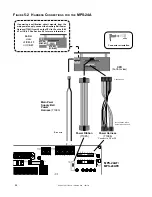
Page 32: ...Bell Power Harness 71091 from J6 on the CPU to J5 on the ICM 4F or ICE 4F See Section 6 9 for more information Connector orientation 7 position end Note position of Red Wire at 8 position end Power Ribbon 71085 Main Pwer Supply Bell Power Harness 71093 Blue wire Power Harness 71086 Connect to P2 or P4 ICM 4F ICE 4F FIGURE 5 2 HARNESS CONNECTIONS FOR THE MPS 24A MPS 24AF MPS 24AFE ...

Page 33: ...se batteries reside in the control panel cabinet Connect the Battery Positive Cable to TB3 Terminal 1 and the Battery Negative Cable to TB3 Terminal 2 Do not connect the Battery Interconnect Cable at this time This connection will be made just after initial primary system power up EARTH FAULT DETECTION The MPS 24BF automatically employs detection of earth faults in the system unless Resistor R55 i...

Page 34: ... Fault Detection Four Wire Smoke Detector Annunciator Power 24 VDC 20 4 26 4 200 mV ripple 200 mA max Filtered regulated and resettable Power limited but when used for four wire detectors must be super vised by a UL listed Power Supervision Relay Notification Appliance power see Caution below 24 VDC power limited RMS regulated non resettable 2 0 amps in alarm max Power is supervised by output modu...

Page 35: ...S CONNECTIONS CPU bottom view 7 position end Power Harness 71086 Connect to P2 Note position of Red Wire at 8 position end Blue wire Black wire Red Wire Power Harness Connector Orientation Power Ribbon 71085 Main Power Supply Bell Power Harness 71093 Connect to J5 on the CPU 2000 ...

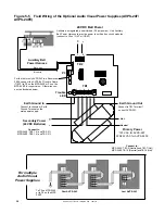
Page 36: ...to notification circuit modules connect to J5 on IC 4F or ICE 4F For multiple Audio Visual Power Supplies Secondary Power 24 VDC Batteries Connect to MPS 24AF TB2 1 and TB2 2 MPS 24BF TB3 1 and TB3 2 Primary Power 120 VAC for AVPS 24F 220 240 VAC for AVPS 24FE Connect to MPS 24AF TB1 5 Neutral andTB1 7 Hot MPS 24BF TB1 3 Neutral andTB1 4 Hot Trouble LED For the first or only AVPS 24F in a Sensisca...

Page 37: ...efer to the R45 24 Product Installation Drawing packaged with each unit CONNECTING THE PRIMARY POWER SOURCE The R45 24 requires 120 VAC 50 60 Hz primary power and the R45 24E requires 220 240 VAC 50 60 Hz primary power With the breaker at the main power distribution panel turned off connect the primary Hot line to Terminal 1 on the R45 24 and the primary Neutral line to Terminal 2 All connections ...

Page 38: ...le UL listed digital alarm commu nicator such as the 911A See Figure 6 1 6 4 DIGITAL ALARM COMMUNICATOR TRANSMITTERS DACT The Fire Alarm Control Panel FACP will support a Digital Alarm Communicator Transmitter DACT provided that the panel is configured and programmed for DACT operation Software P N 73452 or higher will support DACT s that are activated via relay contacts 911A while Software P N 73...

Page 39: ...n u n n A n o i t a r u g i f n o C n o i s i v r e p u S n o i t a r u g i f n o C n o i s i v r e p u S F T C A D U y l n O t i m s n a r T e v i e c e R 5 8 4 A I E a i V F T C A D U d n a r o t a i c n u n n A t i m s n a r T e v i e c e R 5 8 4 A I E a i V 1 s s e r d d A y l n O e v i e c e R d e s i v r e p u S n U y l n O e v i e c e R F T C A D U a i V l i a F m m o C 2 e t o N t u p t u ...

Page 40: ... a 6 32 screw Alternatively the UDACT F may be mounted remotely using an ABS 8RF enclosure Ferrite cores are required for this application Refer to the UDACT F Manual Document 50049 for more information Connect the communication line between the EIA 485 terminal block on the CPU 2000 and TB1 terminals 3 and 4 on the UDACT F being certain to observe polarity refer to the Document 50049 Recommended ...

Page 41: ...iscan 2000 to provide for off premises monitoring of this fire alarm control panel For stand alone installations use the 911AC kit that includes a transformer and an enclosure s for both the 911A and the transformer The 911A is self powered in this mode and is triggered by the alarm and or trouble contacts received from the control panel It communicates with a digital receiver by means of one of t...

Page 42: ...the MS 5012 manual for additional information 2 Program the MS 5012 for slave application AC wiring for the DACT FACP must be connected to the same circuit 1 2 3 4 5 6 7 8 9 10 1112 1314 15 16 1718 19 20 12VDC Battery 2 7AH Red Black 120 VAC HOT Neutral Ground Black White Green yellow yellow 1 2 TB2 TB3 TB1 RESET SILENCE MODE ALARM AC POWER TROUBLE SUPERVISORY Primary Active Secondary Active Kisso...

Page 43: ...ment can be employed for an NFPA 72 1993 Central Station Fire Alarm System NFPA 72 1993 Remote Station Fire Alarm System or NFPA 72 1993 Proprietary Fire Alarm System Form C Trouble contact which will automatically activate on any Trouble condition CPU 2000 Form C Alarm contact programmed to activate on General Alarm Sensiscan 2000 6 7 PROPRIETARY PROTECTIVE SIGNALING The Sensiscan 2000 can be emp...

Page 44: ...or Part 71274 is used on each branch as shown in Figure 6 4 Note This application is not recommended by Factory Mutual FM Figure 6 4 Tee Tapping Notification Appliance Circuits Standard StyleY IC 4F Notification Circuit Module or ICE 4F Expander Tee Tapped Notification Appliance Circuit 4 7K ELR Part 71252 Listed 10K ELR Part 71274 Listed 10K ELR Part 71274 ...

Page 45: ...d wiring 1 The Power Supervision Relay coil leads must be connected to the last detector base 24V screw terminal 2 Calculation of the maximum allowable resistance in the 24VDC detector power wiring RMAX 20 6 VOM N IS NA IA IR RMAX is the maximum total resistance of the 24V power circuits VOM is the minimum operating voltage of the detector or end of line relay whichever is greater in volts N is th...

Page 46: ...e circuits share the total 3 0 amps of current on the AVPS 24F These six Notification appliance circuits share the total main power supply current 6 10 NOTIFICATION APPLIANCE CIRCUIT POWER CONFIGURATIONS The total current drawn from a notification appliance circuit cannot exceed 3 0 amps subject to the limitations of the power supply Figure 6 6 illustrates some of the typical power supply notifica...

Page 47: ...tion appliance cir cuits share 3 0 amps of one AVPS 24F These four notification appliance cir cuits share 3 0 amps of one AVPS 24F These two notification appliance cir cuits share 3 0 amps of one AVPS 24F These two notification appliance cir cuits share total current of the main power supply These two circuits share 3 0 amps of one AVPS 24F These two circuits share 3 0 amps of one AVPS 24F Main Po...

Page 48: ...e all notification appliance circuits and output relays that are mapped to zone 5 with a steady signal Programmed March Time or Temporal code is ignored A fire alarm will take priority over an emergency alert Notification appliance circuit used for fire must be programmed for MTC or Code 3 operation Emergency Alert is for local signalling only do not map to Remote Signalling Municipal Tie outputs ...

Page 49: ...al Inhibit Emergency Alert Acknowledge Signal Silence or System Reset functions can be controlled by a relay contact from a CR 4F CRE 4F Relay Module which can be operated from switches on AFM 16ATX Annunciators 5 Locate Acknowledge Signal Silence and System Reset switches adjacent to a system annunciator so that system status is available to the operator 6 Remote Command Circuits are supervised a...

Page 50: ...eys should be removable in the open position only when used for Acknowledge Signal Silence or System Reset 3 The Presignal Inhibit Emergency Alert Acknowledge Signal Silence or System Reset functions can be controlled by a relay contact from a CR 4F CRE 4F Relay Module which can be operated from switches on AFM 16ATX Annunciators 4 Locate Acknowledge Signal Silence and System Reset switches adjace...

Page 51: ...ring the system we recommend clearing the CPU s memory To do this use the PROGRAM CLEAR function After PREPARING FOR PROGRAMMING enter the password 312 1233 then press and hold the ENTER key The LEDs on the modules will go through a scrolling sequence until finally only the ENTER PASSWORD and PRESS ENTER LEDs are lit approx 10 sec PROGRAM CLEAR is now complete and the system is ready for reconfigu...

Page 52: ...circuit for supervisory The POINT SELECT switches move the pointer to the other initiating circuits When all Supervisory circuits have been programmed press the FUNCTION SELECT switch to store the programming information and advance programming to the next function SILENCEABLE WATERFLOW OPERATION Notification appliance and other output circuits that are activated in response to an alarm on a water...

Page 53: ...TYPE CODE TYPE SELECTION Allows for the selection of March Time Code 110 beats per minute or Temporal 3 3 3 coding for circuits programmed as coded in the previous step Code type selection is on a system basis therefore all coded circuits will sound the same code Circuits that were not selected as coded are unaffected by Code Type selection Special Requirements apply to codes and code type selecti...

Page 54: ... activation of a second automatic fire detector bypasses presignal and immediately activates alarm signals To accomplish this the installer must install one smoke detector per conventional initiating device 4 Zones selected for PAS operation shall contain smoke detectors only These zones may not contain other initiating devices such as manual stations heat detectors waterflow indicators etc A fire...

Page 55: ...forma tion and select the next function I O Map INPUT OUTPUT MAP The I O map is the assignment of output circuits to be activated by par ticular initiating circuits Unmapped initiating circuits will not generate a system alarm Unmapped controlled outputs will not operate Silence Inhibit None 30 sec 60 sec 5 min Programming the I O MAP The I O Map LED will illuminate steadily The red LED pointer wi...

Page 56: ...tion of an alarm condition NFPA 72 1993 requires the installation of a Day Night Weekend switch that can override PAS operation This can be accomplished by using a normally open switch to close an IZ 8F that has been programmed for NON ALARM and SUPER VISORY operation Note that the zone cannot have a notification appliance circuit mapped to it The switch totally inhibits all presignal function On ...

Page 57: ...until the LEDs reflect the desired choice Press the FUNCTION SELECT switch to store the option setting in memory and advance to the next point to be pro grammed Again press the ENTER switch until the LEDs reflect the desired choice followed by the FUNCTION SE LECT switch to store the data To exit extended programming at any time remove the programming key The 123 3211 password does not allow acces...

Page 58: ...tor failure Indicates 1 that a power supply is not functioning correctly 2 AC line voltage is below normal 3 improper battery voltage or 4 that a ground fault exists Additional informa tion is displayed on internal LEDs located on power supply assemblies Indicates that an output circuit is silenced Indication will remain until the reset switch is depressed Indicates that a circuit s within the sys...

Page 59: ...indi cates trouble conditions or disabled outputs New troubles are indicated by a flashing LED 8 1 CPU 2000 CIRCUITS The CPU Module contains 1 Two supervised notification appliance circuits that can be used to control evacuation signaling devices such as bells chimes horns and strobes 2 An alarm relay that can control external devices such as elevators and doors 3 A Remote Signaling Municipal Tie ...

Page 60: ...signaling devices such as bells chimes horns and lights The IC 4F module conveys the status of the notification appliance circuits and their wiring to the CPU module and at the direction of the CPU will light the appropriate LEDs to display activation and trouble condi tions broken wire inactive circuit The notification appliance circuits activate automatically during an alarm condition according ...

Page 61: ...d or reverse until the pointer stops at the circuit to be disabled 4 Press Switch 1 ACKNOWLEDGE to turn on the left hand LED on the circuit to be disabled When this LED is on the circuit has been disabled A circuit can be re enabled by pressing Switch 1 until the left hand LED goes out 5 Repeat steps 3 and 4 until all disabling enabling has been accomplished 6 Release the LAMP TEST switch to exit ...

Page 62: ...t the green AC POWER LED is illuminated 2 Check that all yellow LEDs are off 3 Holding SYSTEM RESET depressed should sequentially light all system LEDs 4 Before proceeding a notify fire department and or central alarm receiving station if alarm conditions are transmit ted b notify facility personnel of test so that alarm sounding devices are ignored during test period When necessary activation of ...

Page 63: ... the battery leads can damage the battery equipment and could cause injury to personnel 9 5 WALK TESTING THE SENSISCAN 2000 In order to execute Walk Test from the Sensiscan 2000 the CPU Programming Key must be inserted Enter the Walk Test password 123 1233 then press ENTER Depress the Enter Switch again The PASSWORD AC CEPTED LED will light and the WALK TEST LED will flash Activate an initiating d...

Page 64: ...p regulated output for powering four wire smoke detectors The MPS 24BF provides 750 mA of regulated power for system modules and 2 0 amps for Notification Appliances A 1 THE FIRE ALARM CIRCUIT The control panel requires connection to a separate dedicated AC fire alarm circuit which must be labeled FIRE ALARM This circuit must connect to the line side of the main power feed of the protected premise...

Page 65: ...ain power supply during a fire alarm condition with primary power applied This current drawn during a fire alarm cannot exceed 0 750 amps on the MPS 24BF This column does not account for current draw from TB2 3 and TB2 4 in fire alarm which is limited to 2 0 amps exclusive of the 0 750 amps fire alarm load The fire alarm load cannot exceed 6 amps for the MPS 24AF and 2 3 amps for the MPS 24BF Note...

Page 66: ... x 5 6 0 0 x 5 6 0 0 x 2 7 0 0 x 7 4 0 0 x 4 0 0 0 x 7 0 0 0 x 1 0 0 0 x e l b a c i l p p a t o n 7 0 0 0 x F A 2 3 M F A F T A 6 1 M F A F A 2 3 M C A F T A 6 1 M C A F A 6 1 M F A o t r e f e r X A 2 3 M F A X T A 6 1 M F A 0 9 3 5 1 c o D 0 4 0 0 x 0 4 0 0 x 5 2 0 0 x x 6 5 0 0 x 6 5 0 0 x 5 6 0 0 x x 0 4 0 0 x 0 4 0 0 x 5 2 0 0 x x r e f e r s r o t c e t e D e k o m S e r i W 2 y t i l i b i...

Page 67: ...rm Batteries installed in a system powered by a generator need to provide at least four hours of standby power 2 If the total exceeds 55AH 17AH on the MPS 24BF a UL listed Uninterruptable Power Supply UPS with sufficient capacity is needed If the system does not have battery backup a UPS must be installed in the same room as the FACP Table A 2C Secondary Power Standby and Fire Alarm Load Table A 2...

Page 68: ...charger range Battery Charger Amp Hour Range MPS 24AF 9 55AH MPS 24BF 6 5 17AH y r e t t a B e z i S e g a t l o V g n i t a R r e b m u N d e r i u q e R t r a P r e b m u N e z i S t e n i b a C H A 0 7 H A 5 9 H A 2 1 H A 7 1 H A 5 2 H A 5 5 s t l o v 2 1 s t l o v 6 s t l o v 2 1 s t l o v 2 1 s t l o v 2 1 s t l o v 2 1 o w t r u o f o w t o w t o w t o w t 0 7 2 1 S P 5 9 6 S P 0 2 1 2 1 S P...

Page 69: ... S y r o s i v r e p u S V A l a u s i V o i d u A N m r a l A n o N M S R e t o m e R l a p i c i n u M n o i t a t S T e i T e l u d o M n o i t i s o P t i u c r i C r e b m u N l e b a L t i u c r i C g n i t a i t i n I e n o Z e p y T m r a l A y f i r e V s t i u c r i C n o i t a c i f i t o N d e p p a M s t i u c r i C 0 0 0 2 U P C n o i t s i s o P e l u d o M t u p t u O r e t n E t i...

Page 70: ... 0 2 U P C A 1 B 1 C 1 D 1 A 2 B 2 C 2 D 2 s g n i t t e S e d i W m e t s y S e p y T e d o C q l a r o p m e T q e m i T h c r a M t i b i h n I e c n e l i S q e n o N q c e s 0 3 q n i m 1 q n i m 5 e c n e l i S m r a l A q e n o N q n i m 5 q n i m 0 1 q n i m 0 2 y a l e D l a n g i S e r P q e n o N q n i m 1 q n i m 2 q n i m 3 d n e g e L e p y T e n o Z e n O r e t n E r e t t e L e p y...

Page 71: ...S2000 15017 Rev H 10 08 96 P N 15017 H 71 Notes ...

Page 72: ...ng constitutes the only warranty made by Fire Lite with respect to its products Fire Lite does not represent that its products will prevent any loss by fire or otherwise or that its products will in all cases provide the protection for which they are installed or intended Buyer acknowledges that Fire Lite is not an insurer and assumes no risk for loss or damages or the cost of any inconvenience tr...

Page 73: ...ot function for the in hibit time marked at right ACKNOWLEDGE SILENCE TONE Depressing the ACKNOWLEDGE switch will turn the audible tone off and switch operation of associated LED s from flashing to steady New alarms and or troubles will resound the audible tone and flash their associated LED s ALARM SILENCING PROCEDURE Alarm notification appliance circuits control relays and signalling circuits th...

Page 74: ...ABLE 1 2 3 CPU LABELS Programming Operating left Operating right Slide In Labels for the Fire Lite Sensiscan 2000 Fire Alarm Control Panel These pages contain slide in labels for the Sensiscan 2000 Remove these pages and carefully cut out the labels for insertion in the CPU 2000 modules and the VP 1F dress panel The labels slip into the back side of the CPU s faceplated and the back side of the VP...

Reviews:

Related manuals for SENSISCAN 2000