background image


-                                                                      5 - 


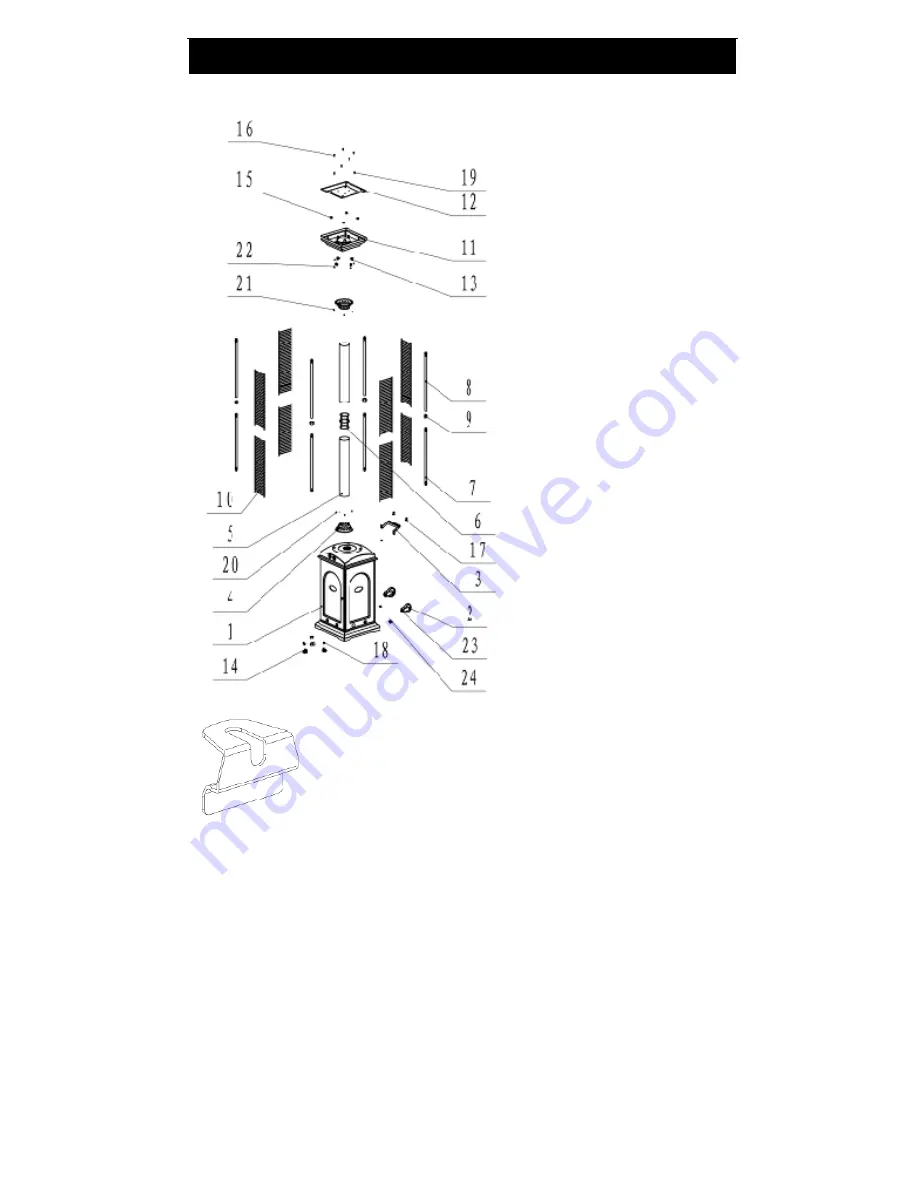
1.


Base assembly with 

tank and control 
housing 

2.


2pcs wheels 

3.


Handle 

4.


2pcs glass tube fixed 
parts (one for top, one 

for bottom) 

5.


2pcs glass tube 

6.


Glass tube connector 

7.


4pcs lower support 

8.


4pcs upper support 

9.


4pcs support connector 

10.


8pcs mesh guard 

11.


Upper plate 

12.


Top reflector 

13.


4pcs mesh fixed parts 
(see exploded view 
below) 

14.


3pcs gas cylinder fixed 
parts and 3pcs 
M8x25mm bolts (to   
secure LPG cylinder on 

base) 

15.


4pcs M12 screws 

16.


4pcs M5x10mm bolts 

17.


4pcs M6x12mm bolts 

18.


6pcs M6x12mm bolts 

19.


3pcs 3/16’’ screws 

20.


3pcs M4x8mm screws 

21.


3pcs M4x8mm screws 

22.


4pcs M4x8mm screws 

23.


8pcs M6x18mm bolts 

24.


8pcs M6 nuts 


                                                                                                  ASSEMBLY 


# 13 (exploded view) 

Summary of Contents for PH08-SA

Page 1: ...ace Co Ltd WARNING For outdoor use only FOR YOUR SAFETY If you smell gas 1 Shut off gas to the appliance 2 Extinguish any open flame 3 If odor continues immediately call gas supplier FOR YOUR SAFETY D...

Page 2: ...ned off and removed NOTE Use only 20lb LP Gas tank with size of 18 1in 46cm Height 12 5in 32cm Width Do not use if the environment temperature is below 40 degrees F 4 4 degrees C WARNING Improper inst...

Page 3: ...ored Prior to use check for damaged parts such as hoses regulators pilot or burner Turn off and disconnect LPG cylinder before moving the heater Do not attempt to alter this heater in any manner EXAMP...

Page 4: ...r to operating the heater Installation and repair should be done by a qualified service person The heater should be inspected before use and cleaning may be required at least once a year or as necessa...

Page 5: ...nnector 10 8pcs mesh guard 11 Upper plate 12 Top reflector 13 4pcs mesh fixed parts see exploded view below 14 3pcs gas cylinder fixed parts and 3pcs M8x25mm bolts to secure LPG cylinder on base 15 4p...

Page 6: ...person Proper assembly is the responsibility of the installer Step 1 Attach the wheels 2 to the base assembly 1 with 8pcs M6x18mm bolts 23 and 8pcs M6 nuts 24 Step 2 Attach the handle 3 to the back pa...

Page 7: ...Step 3 Attach one of the glass tube fixed parts 4 on the base assembly 1 with 3pcs M4x8mm screws 20 Step 4 Screw the 4pcs lower support 7 into the holes located on the top of the base assembly 1 ASSEM...

Page 8: ...8 Step 5 Put the 4pcs of the support connector 9 onto the tops of the 4 lower supports 7 Step 6 Screw the 4 upper supports 8 onto the 4 lower supports 7 ASSEMBLY...

Page 9: ...e assembly 1 Insert the glass tube connector 6 into the glass tube piece already attached to the base assembly and then lower the second piece of glass tube over the glass tube connector Step 8 Attach...

Page 10: ...r plate from Step 8 on top of the assembled support connectors and use 4pcs M12 screws 15 to secure it Step 10 Attach 4pcs mesh guard 10 on the lower support connectors NOTE The long side will connect...

Page 11: ...11 Step 11 Attach 4pcs mesh guard 10 on the upper support connectors Step 12 Attach 4pcs mesh fixed parts 13 on the assembled upper plate with 4pcs M4x8mm screws 22 ASSEMBLY...

Page 12: ...eflector 12 on the assembled upper plate with 3pcs 3 16 screws 19 and 4pcs M5x10mm bolts 16 Step 14 Open the front panel of base assembly 1 Attach 3pcs gas cylinder fixed parts 14 on the base with 6pc...

Page 13: ...urner to the LPG cylinder and hand tighten then put gas cylinder on the base Warning When connecting the gas cylinder and regulator make sure the connection is tight and always check for leaks Please...

Page 14: ...Spoon several drops or use squirt bottle of the soapy solution onto the gas hose regulator and regulator cylinder connection 4 Inspect the connections and look for bubbles 5 If no bubbles appear the...

Page 15: ...linder valve Annually check operation A Open the front panel of the base assembly B Open the propane tank valve C Spoon several drops or use squirt bottle of the solution onto gas hose connection and...

Page 16: ...re free of combustible materials such as gasoline and other flammable vapors or liquids Ensure that there is no obstruction to air ventilation Be sure all gas connections are tight and there are no le...

Page 17: ...ow at least one minute or more for the air in the gas pipeline to purge out through the pilot hole When lighting the pilot flame make sure that the control knob is continuously depressed while pressin...

Page 18: ...king areas This heater is for outdoor use ONLY Always make sure that adequate fresh air ventilation is provided and follow the spacing tolerances shown in the picture below The minimum clearances must...

Page 19: ...t once a year the unit should be inspected for the presence of spiders spider webs or other insects Air flow must be unobstructed Keep controls burner and circulating air passageways clean Signs of po...

Page 20: ...ermocouple bad Replace thermocouple Gas leak in line Check connections Lack of fuel pressure Fuel tank is near empty Burner will not light Pressure is low Fuel tank is near empty Control valve not ON...

Page 21: ...N THIS MANUAL CAN RESULT IN SEVERE PROPERTY DAMAGE AND OR PERSONAL INJURY IN NO EVENT WILL WELL TRAVELED LIVING OR ITS DIRECTORS OFFICERS OR AGENTS BE LIABLE TO THE PURCHASER OR ANY THIRD PARTY WHETHE...

Reviews: