EQUIPMENT:
FIRE
CLASS
DUO-CEL
PUBLICATION:
OM_DUO-CEL_APP
ISSUE No. & DATE:
2 20/06/18
PAGE 13 of 46
6. Power Supply
6.1
General
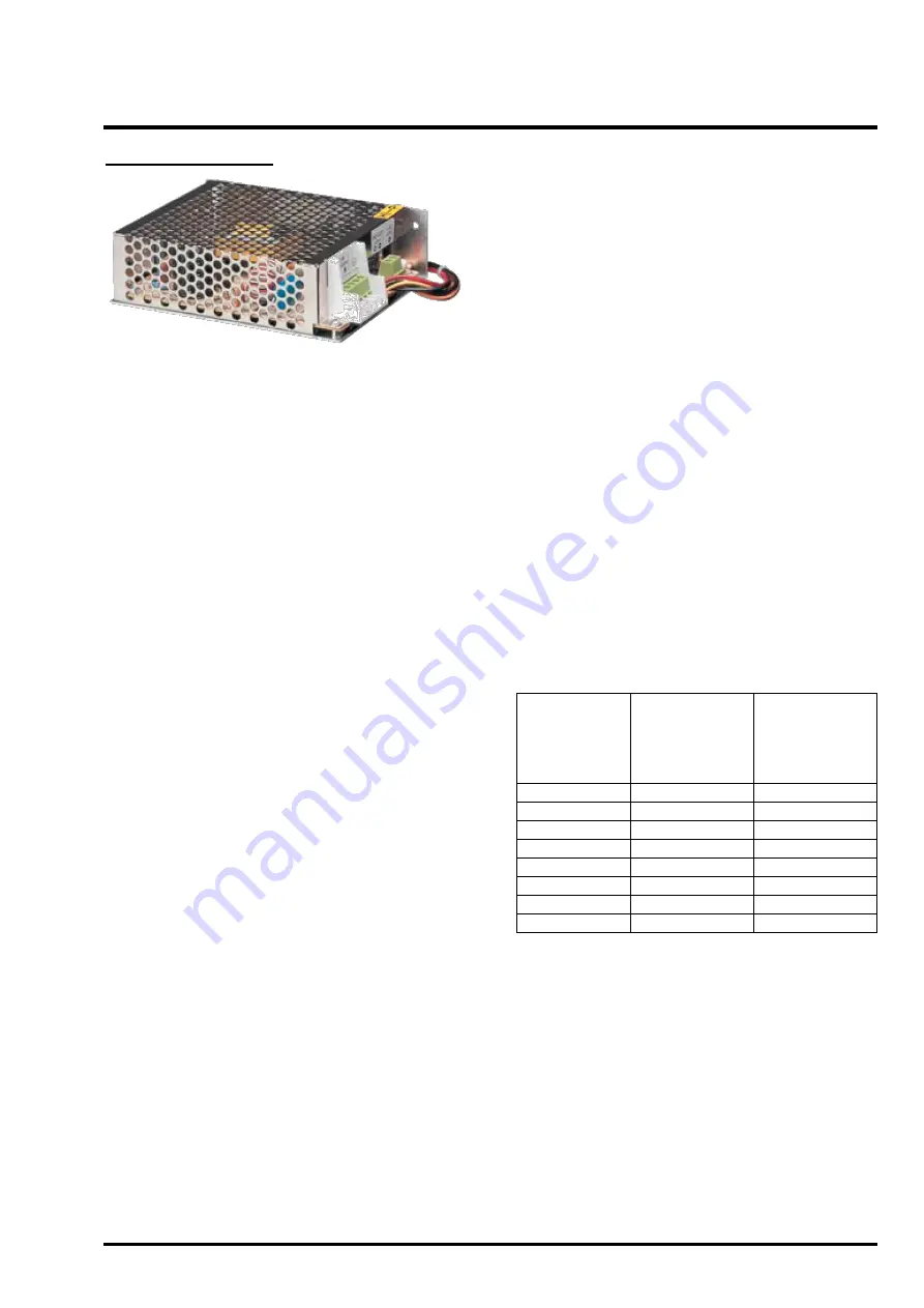
The DUO-CEL uses a BENTEL BAQ35T24 switch
mode Power Supply which has the following
features:
Input voltage: 230 VAC 50/60Hz
Output voltage: 27.15VDC (nominal @ 25
o
C)
Stability over 1% with full load
Overload protection
Short-circuit protection
Insulation class 1
Tested and approved to EN 60950:1996 +
A4:1997
Dimensions: 130mm x 100mm x 38mm
Weight: 389g
The battery monitoring circuit is part of the control
board. This provides:
Thermistor for temperature compensation
Battery/charger fault monitoring
Automatic
“battery
disconnect
”
facility.
Disconnects the battery when the battery
terminal voltage falls below 21.6V, to prevent
deep discharge of the batteries if supplying the
panel for an abnormally long period of time.
6.1.1 Supply Input
The PSU is designed to run from mains voltage at
230Vac +10%, -15%, 50/60Hz. The input is
protected by a 3A 20mm glass fuse. The fuse is
inside the metal cage and is not user-serviceable.
6.1.2 Supply Output
The output from the PSU is 27.15Vdc ±1% at 25°C
with load up to 1.5A. The output is protected by a
6.3A 20mm glass fuse. The fuse is inside the metal
cage and is not user-serviceable.
The output current is shared between the panel
load and battery charging. The battery charging
current is therefore dependent on output current
and will fall to zero as the panel load approaches
1.5A.
The output is connected to the panel via a three-
wire flying lead, providing the DC power and a fail-
safe fault signal.
6.1.3 Battery Charger
The power supply is capable of charging 2-off 12V
3.4Ah SLA Powersonic PS-1230 batteries.
The power supply unit monitors a Thermistor on the
panel control board and automatically adjusts the
output voltage to provide the optimum safe
charging voltage over an operating temperature
range of -5
o
C to +40
o
C.
The charging voltage can be adjusted via the
trimmer potentiometer VR1 on the PSU. However,
the charging voltage is factory set and adjustment
should not be necessary (a 15K resistor can be
used in place of the Thermistor to simulate 25
o
C).
NOTES:
1. The battery charging voltage is temperature
dependant and should be set as detailed in
Table 2. Charging at too high a voltage may
result in overheating, resulting in damage to
the batteries. Charging at too low a voltage
will result in insufficient charging of the
batteries.
2. The charging profile of the power supply unit
is optimised for Powersonic
™ batteries and
c
harging of other manufacturers’ batteries is
not recommended. Consult your battery
supplier or battery manufacturer before use.
Table 2
– Float Charge Voltages for
Powersonic VRLA batteries
Ambient
Temperature
Charger Set
voltage (V)
Float Charge
Voltage (V)
(2x12V
Batteries in
series)
-10
o
C (14
o
F)
28.32
– 28.42
27.84
– 28.44
0
o
C (32
o
F)
27.82
– 27.92
27.60
– 28.20
10
o
C (50
o
F)
27.45
– 27.55
27.36
– 27.96
20
o
C (68
o
F)
27.20
– 27.30
27.12
– 27.72
25
o
C (77
o
F)
27.10
– 27.20
27.00
– 27.60
30
o
C (86
o
F)
27.03
– 27.13
26.88
– 27.48
40
o
C (104
o
F)
26.91
– 27.01
26.64
– 27.24
50
o
C (122
o
F)
26.84
– 26.94
26.40
– 27.00
6.1.4 Battery Monitoring
The health of the batteries, the battery connections
and fuse are checked by a battery monitor circuit on
the panel control board.
The batteries are monitored for disconnection. If
the battery voltage falls to 18V or below then a
PSU fault is raised and the charging voltage is
removed from the terminals.
The batteries are monitored for low voltage. If
the battery voltage drops below 21.6V when the
mains power is disconnected, then the
batteries
are electronically disconnected to prevent deep
discharge. The batteries are reconnected only
after mains power is restored.
The batteries are monitored periodically for high


