EQUIPMENT:
FIRE
CLASS
DUO-CEL
PUBLICATION:
OM_DUO-CEL_APP
ISSUE No. & DATE:
2 20/06/18
PAGE 24 of 46
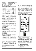
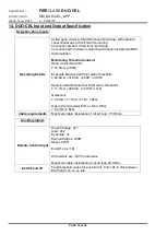
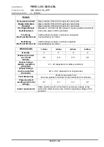
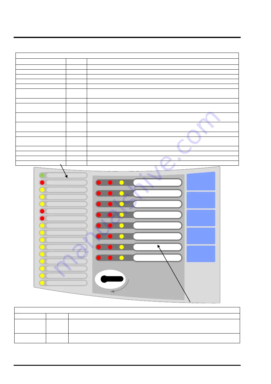
10.1 Repeater User Indications
SILENCE
BUZZER
SILENCE /
RESOUND
ALARMS
RESET
TEST
EVACUATE
SUPPLY ON
GENERAL FIRE
GENERAL FAULT
GENERAL TEST
GENERAL DISABLE
ALERT / EVAC ON
FIRE SIGNAL ON
FIRE SIGNAL FAULT
SNDR FLT / DIS / TEST
REPEATER FAULT
REPEATER PSU FAULT
PANEL PSU FAULT
EARTH FAULT
COMM FAULT
REMOTE I/P FAULT
CONTROLS ON
1
2
3
4
5
6
7
8
General Indicator Section
Indicator
Colour
Operating Condition
Supply On
Green
OFF
: No mains or battery power,
ON
: Panel has power (battery and/or mains)
General Fire
Red
OFF
: Quiescent,
FLASH
: New Alarm Condition,
ON
: Alarm Accepted
General Fault
Yellow
OFF
: No faults present,
FLASH
: One or more faults present
General Test
Yellow
OFF
: No circuits in Test,
ON
: One or more circuits in Test
General Disablement
Yellow
OFF
: No circuits Disabled,
ON
: One or more circuits Disabled
Alert/Evac On
Red
OFF
: No Alert or Evacuate,
FLASH
: Remote Alert active.
ON
: Remote Evacuate
active
Fire Signal On
Red
OFF
: Fire Signal output not active,
ON
: Fire Signal output active
Fire Signal Flt / Dis / Tst
Yellow
OFF
: No fault on Fire Signal output,
FLASH
: Fault on Fire Signal output,
ON
: Fire Signal output Disabled or in Test
Sounder Flt / Dis / Tst
Yellow
OFF
: No Fault on Sounder circuits,
FLASH
: Fault on one or more Sounder
circuits,
ON
: Sounder circuits Disabled or in Test
Repeater Fault
Yellow
OFF
: Repeater is working correctly,
ON
: Repeater is in the SAFE state
(Microcontroller failed)
Repeater PSU Fault
Yellow
OFF
: Power supply is healthy,
FLASH
: PSU fault and/or battery fault
Panel PSU Fault
Yellow
OFF
: Panel power supply is healthy,
FLASH
: Panel PSU has fault or Auxiliary
24Vdc output fuse activated
Earth Fault
Yellow
OFF
: No cable faults to Earth,
FLASH
: One or more cable faults to Earth
Communication Fault
Yellow
OFF
: Communication with Panel,
FLASH
: No communication with Panel
Remote Control Fault
Yellow
OFF
: No faults on Remote Control input,
FLASH
: Fault on Remote Control input
Controls On
Green
OFF
: User Controls disabled,
ON
: User Controls enabled
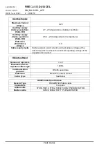
Zone Location Indications
Indicator
Colour
Operating Condition
User Zone
Location Text
Red
OFF
: No Alarm on zone,
FLASH
: New Alarm on zone,
ON
: Alarm accepted on zone.
NOTE: With Detector/MCP discrimination, the left LED is for Detectors, the right LED for
MCPs.
User Zone
Location Text
Yellow
OFF
: No Fault on zone circuit, FLASH: Fault on zone circuit,
ON
: Zone circuit Disabled or in
Test


