EQUIPMENT:
FIRE
CLASS
DUO-CEL
PUBLICATION:
OM_DUO-CEL_APP
ISSUE No. & DATE:
2 20/06/18
PAGE 28 of 46
11.7 Remote Control Input
A single 2-terminal input allows remote operation of
the following functions:
Control
Level
Function
Control
Resistor
1
Class Change
4K7
2
Alert
2K2
3
Evacuate
1K
4
Remote Silence
Alarms
470R
5
Remote Reset
220R
Control Level 1 is lowest priority, 5 is highest
priority.
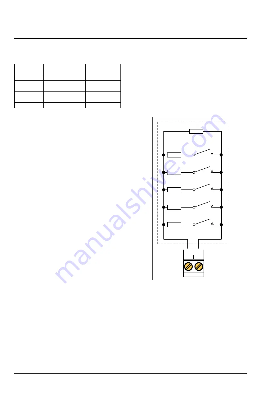
The input is monitored for open and short circuit
faults. Each control level requires a different
resistor load as shown in the above table. A 10K
resistor acts as the end-of-line device for fault
monitoring. See Figure 10 for wiring details.
11.7.1 Class Change
The Class Change function allows all sounder
circuits to be operated for a maximum of 5 seconds.
When the Class Change control resistor is applied,
the sounders will operate continuously and then
automatically
silence
after
5
seconds.
No
indications will be given on the panel. The resistor
needs to be removed and applied again if the signal
needs to be repeated.
11.7.2 Alert
The Alert function allows all sounder circuits to be
operated in pulsing mode.
When the Alert resistor is applied, the
sounders will
pulse until the resistor is removed. The Alert/Evac
On LED will illuminate on the panel and the internal
buzzer will sound.
11.7.3 Evacuate
The Evacuate function allows all sounder circuits to
be operated in continuous mode.
When the Evacuate resistor is applied, the
sounders will operate continuously until the resistor
is removed. The Alert/Evac On LED will illuminate
on the panel and the internal buzzer will sound. The
Evacuate output will also operate.
11.7.4 Silence Alarms
The Silence Alarms function allows all active
sounder circuits to be deactivated.
When the Silence Alarms resistor is applied, any
active sounder circuits will be deactivated. The
Silence Alarms function is momentary and the
resistor needs to be removed and applied again in
order to re-operate the Silence Alarms function.
11.7.5 Reset
The Reset function allows all standing alarms and
faults to be cleared, returning the panel to the
quiescent state. The Auxiliary 24VDC supply may
also be switched off for 10 seconds if configured to
do so.
When the Reset resistor is applied with the panel in
the fire alarm condition, any active sounder circuits
will be deactivated, all zone circuits will reset the
detectors, the fire relay will de-energise, the fault
relay will deactivate and all fire and fault indications
will clear. The Reset function is momentary and the
resistor needs to be removed and applied again in
order to re-operate the Reset function.
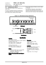
Figure 10
– Remote Control I/P connections
220R ¼ W
RESET
470 ¼ W
SILENCE
ALARMS
1K ¼ W
EVACUATE
10K ¼ W EOL
REMOTE
I/P
0V
2K2 ¼ W
ALERT
4K7 ¼ W
CLASS
CHANGE
Note:
To prevent unauthorised operation of the
system, any manually operated function must
be operated by a key-switch. The key to the
switch should be held with the panel’s access
control key.
For
the
SILENCE
ALARMS
and
RESET
functions, the Keyswitch should be spring-
biased so that it automatically returns to the off
position when released.
11.8 Open Collector Outputs
Three open collector outputs are provided:
1. Disabled (DIS.)
2. Evacuate (EVAC.)
3. Buzzer Active (BUZ.)


