FIRECLASS FC490ST
3.4 Button Operation
User Manual Doc. version 2
9
Ancillaries are connected to the ‘AUX’ socket using the
ancillary connector lead.
3.4
Button Operation
The screen displays the start of the main menu as shown in
Fig. 5.
The main menu can always be identified by the word
Select
between two arrows on the top line of the display.
The bottom line of the main menu displays the option.
The top line position of text is always shown in relation to
the F1-F4 buttons above. In the Main Menu:
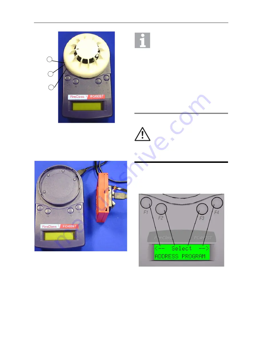
Fig. 3: Connecting to a detector
1 –Marking
2 –Position 2
3 –Position 1
Fig. 4: Connecting to an ancillary
1
2
3
Preferable Connections
It is good practice to:
Connect only a detector or an ancillary at any
one time. However, the FC490ST is
equipped with a port interlock feature. When
the ancillary lead is connected to the ‘AUX’
socket, communication with the detector will
be disabled. When the ancillary lead is
removed, the detector will be able to commu-
nicate.
The FC490ST may be connected to an ancil-
lary device that is also connected to and pow-
ered from the addressable loop. However, a
‘No Response’ fault for that device may be
generated at the Control Panel under these
conditions.
WARNING
Danger from electric shock
Special care must be taken when
connecting to a device on the
addrsesable loop to prevent unwanted
action in other equipment, for example,
extinguishing systems.
Fig. 5: First Display Screen of the main menu


