EQUIPMENT:
FIRE
CLASS
PRECEPT EN
WRITTEN BY: RKP
PUBLICATION:
FIRECLASS PREC EN OUTPUT EXP MOD INST
CHECKED BY: AP
ISSUE No. & DATE:
0 02/03/12
PAGE 11 of 21
7. Commissioning
The commissioning guidelines provided in the
FIRE
CLASS
Precept EN panel installation manual.
adequately cover the requirements for the output
modules and should be read and understood before
proceeding.
7.1 Site-Specific Configuration
DIL switches are provided on the C1630 interface
board to set up the quantity of each type of output
expansion module to be connected to the fire panel
and on each output module to set the module
address and configure its function.
7.1.1 C1633 8-way open collector
output module configuration.
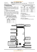
Table 3
– Setting C1633 Board Address
SW1
Function
AD0
AD1
Board Address
Off
Off
1
On
Off
2
Off
On
3
On
On
4
Table 4
– Setting C1633 Zone Range
SW1
Function
Zonal
ZN0
ZN1
O/P 1-8 zone range
Off
Not
functional
Not
functional
All O/Ps operate on
any zonal fire
On
Off
Off
Z 1-8
On
On
Off
Z9-16
On
Off
On
Z17- 24
On
On
On
Z25 -32
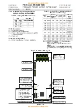
C1633 Connectors:
J1
– Programming header.
J2
– Comms to panel motherboard.
J3
– Power out.
J4
– Power in [from panel motherboard or aux PSU]
+ Aux PSU fault I/P.
C1633 Link Configuration:
J5
– Fit link to enable Aux PSU fault monitoring.
Figure 8
– C1633 PCB Layout
ZONAL
ZN1
ZN0
AD1
AD0
1
2
3
4
5
SW1
J3
0
V
+
2
4
0
V
+
2
4
J4
J6
J2
J5
S
W
2
PROC FAULT
RESET
C
O
M
S
F
L
T
P
R
O
C
F
L
T
P
S
O
N
POWER
FAULT
ENABLE
C
E
L
C
1
6
3
3
IS
S
U
E
2
0
5
-0
5
-2
0
0
5
O
P
E
N
C
O
L
L
E
C
T
O
R
O
U
T
P
U
T
B
O
A
R
D
+
2
4
V
+
2
4
V
O
P
1
O
P
2
O
P
3
O
P
4
O
P
5
O
P
6
O
P
7
O
P
8
24Vdc Output
J2 Comms In/Out
J6 Comms In/Out
Open Collector
Outputs 1 to 8
J5
– Fit link to
enable Auxiliary
Power Supply Fault
monitoring
SW2
– Processor
Fault Reset Button
Power Supply ON LED
Processor Fault LED
Communication Fault LED
J4
– 24Vdc Power
In from panel or
Aux PSU, with
optional PSU fault
monitoring inputs
J3
– 24Vdc output
to other modules
SW1
– Configuration Switch.
AD0
– Address bit 0
AD1
– Address bit 1
ZN0
– Zone range bit 0
ZN1
– Zone range bit 1
ZONAL
– Zonal response


