EQUIPMENT:
FIRE
CLASS
PRECEPT EN
WRITTEN BY: RKP
PUBLICATION:
FIRECLASS PREC EN OUTPUT EXP MOD INST
CHECKED BY: AP
ISSUE No. & DATE:
0 02/03/12
PAGE 13 of 21
7.1.2 C1635 8-way alarm/monitored
output module configuration.
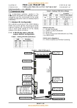
Table 8
– Setting C1635 Board Address
SW1
Function
AD0
AD1
Board Address
Off
Off
1
On
Off
2
Off
On
3
On
On
4
C1635 Connectors:
J1
– Programming header.
J2
– Comms to panel motherboard.
J3
– Power in [from panel motherboard or aux PSU]
+ Aux PSU fault I/P.
J5
– Power out.
C1635 Link Configuration:
J4
– Fit link to enable Aux PSU fault monitoring.
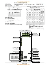
Table 9
– Setting C1635 Type, General/Zonal
Response and Zone range
SW1/6
[FP]
Mode
Panel
Board
SW2/6
SW1
Zonal
SW1
ZN0
SW1
ZN1
O/P 1-8
zone
range
Off
SNDR
Off
N/A
N/A
N/A
All O/Ps
operate on
any fire
Off
SNDR
On
On
Off
Off
Z1-8
Off
SNDR
On
On
On
Off
Z9-16
Off
SNDR
On
On
Off
On
Z17- 24
Off
SNDR On
On
On
On
Z25 -32
On
FP
N/A
Off
N/A
N/A
All O/Ps
operate on
any fire
On
FP
N/A
On
Off
Off
Z1-8
On
FP
N/A
On
On
Off
Z9-16
On
FP
N/A
On
Off
On
Z17- 24
On
FP
N/A
On
On
On
Z25 -32
Notes: SNDR = Sounders,
FP = Fire Protection
When panel SW 2/6 is on:
If panel SW2-7 is off, non-alarm zones are
silent.
If panel SW2-7 is on, non-alarm zones pulse
[See
FIRE
CLASS
Precept EN panel manuals]
Figure 10
– C1635 PCB Layout
+ OP1 -
ZONAL
ZN1
ZN0
AD1
AD0
1
2
3
4
5
SW1
J3
0
V
+
2
4
0
V
+
2
4
J4
J6
J2
J5
S
W
2
PROC FAULT
RESET
C
O
M
S
F
L
T
P
R
O
C
F
L
T
P
S
O
N
POWER
FAULT
ENABLE
CEL C1635 ISSUE 2 05-05-2005
8
W
A
Y
M
O
N
O
/P
B
D
J2 Comms In/Out
J6 Comms In/Out
J4
– Fit link to
enable Auxiliary
Power Supply Fault
monitoring
SW2
– Processor
Fault Reset Button
Power Supply ON LED
Processor Fault LED
J3
– 24Vdc Power In
from panel or Aux PSU,
with optional PSU fault
monitoring inputs
J5
– 24Vdc output to
other modules
SW1
– Configuration Switch.
AD0
– Address bit 0
AD1
– Address bit 1
ZN0
– Zone range bit 0
ZN1
– Zone range bit 1
ZONAL
– Zonal response
FP
– Fire Protection
Outputs
+ OP2 - + OP3 - + OP4 -
+ OP5 - + OP6 - + OP7 - + OP8 -
6
FP
Communication
Fault LED
1
OUTPUT FAULTS
2
3
4
5
6
7
8
Outputs 1 to 8
(Top row = 1 to 4,
Bottom row = 5 to 8)
Fault LEDs for each output


