EQUIPMENT:
FIRE
CLASS
PRECEPT EN
WRITTEN BY: RKP
PUBLICATION:
FIRECLASS PREC EN OUTPUT EXP MOD INST
CHECKED BY: AP
ISSUE No. & DATE:
0 02/03/12
PAGE 3 of 21
1. Introduction
This document contains all the information
necessary for the installation, commissioning and
maintenance of the
FIRE
CLASS
Precept EN
range
of output expansion panels. Installation and
commissioning details for Precept EN fire detection
and alarm panels are covered in the
FIRE
CLASS
Precept EN manuals mentioned below.
NOTE: It is important to read this manual fully
before commencing installation.
The following supporting documentation is also
available:
FIRE
CLASS
Precept EN
Output Expansion
System Application Guide
FIRE
CLASS
Precept EN Panel Application
Guide
FIRE
CLASS
Precept EN
User Manual
Wiring Recommendations
2. Overview of Installation and
Commissioning
This section lists the steps that are taken in
installing and commissioning a Precept EN
output
expansion system.
1. Install all field wiring and equipment
Refer to the Installation Guidelines in section
Refer to the field device installation manuals
2. Install the panel
Refer to the installation instructions in section
Do not connect the field equipment at this
stage.
3. Commission the panel
Refer to section 6.
3. Power Supplies
The
FIRE
CLASS
Precept EN 8-Zone fire alarm
panel utilises the standard 230Vac 3A PSU fitted to
the C1627 motherboard. The
FIRE
CLASS
Precept
EN 16L fire alarm panel uses the C1652 230Vac 5A
PSU mounted on the internal chassis beneath the
motherboard & output modules.
FIRE
CLASS
Precept EN Exp 4 and 5 output expansion panels
are supplied with or without a C1652 230Vac 5A
PSU depending on the output load requirement.
When fitted, the PSU is located on the chassis
underneath the output modules.
For all panels, the output voltage is adjustable from
25Vdc to 28.2Vdc via a small trimmer potentiometer
on the PCB. As the output voltage is factory set
however, adjustment should not be necessary.
Details of the PSUs can be found in the
FIRE
CLASS
Precept EN manuals.
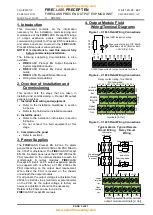
4. Output Module Field
Wiring/Terminal Diagrams
Figure 1
– C1633 Field Wiring Connections
2
k
2
0
.5
W
re
s
is
to
r
C1633 Open collector output module terminals
Typical LED indication wiring
Max current sink into O/P: 60mA
Max load on 24V [total for both
+24V O/Ps]: 0.5A
+
2
4
V
+
2
4
V
O
P
1
O
P
2
O
P
3
O
P
4
O
P
5
O
P
6
O
P
7
O
P
8
Figure 2
– C1634 Field Wiring Connections
Lower
terminal
tier
Middle
terminal
tier
Upper
terminal
tier
C1634 Volt free relay output module
terminals [3- tier]
Relay contact rating: 1A at 30Vdc
Do not exceed
OP1 OP2 OP3 OP4 OP5 OP6 OP7 OP8
N
/C
N
/O
P
O
L
E
Figure 3
– C1635 Field Wiring Connections
+ OP1 -
+ OP2 -
+ OP3 -
+ OP4 -
+ OP5 -
+ OP6 -
+ OP7 -
+ OP8 -
Lower
terminal
tier
Upper
terminal
tier
C1635 powered/fault monitored
output module terminals [2- tier]
3k9 resistor
end-of-line
Typical Alarm
Circuit Wiring
I/P polarised
[All sounder
devices]
3k9 resistor
end-of-line
Typical Remote
Relay Circuit
Wiring
Suppression diode
Polarising diode
+
+
-
-
+
+
-
-


