EQUIPMENT:
FIRE
CLASS
PRECEPT EN13
PUBLICATION:
FIRECLASS PREC EN13 INST
ISSUE No. & DATE:
2 22/07/2021
PAGE 8 of 32
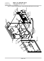
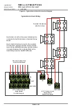
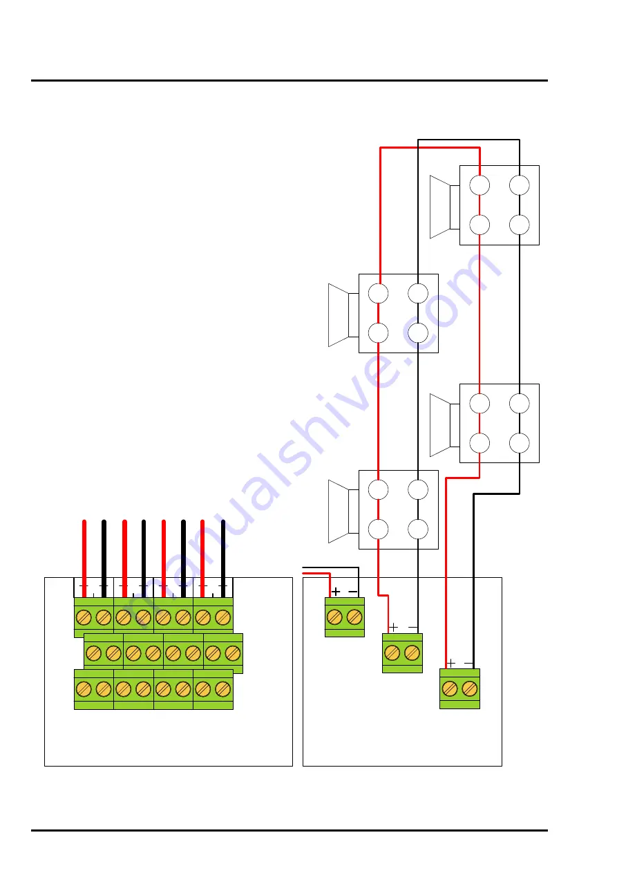
Figure 6 – Typical Alarm Circuit Connection Diagram
Typical Alarm Circuit Wiring
1
2
3
4
C1717 Alarm Circuit
Relay Board
Terminal Layout
IN
OUT
RETURN
OUT
RETURN
Pre-wired cables from
Panel motherboard
-
-
+
+
Each Alarm circuit from the panel motherboard is
connected to the IN terminals on the Alarm Relay
Board.
Each Alarm Circuit is wired out to the sounders
from the OUT terminals and the circuit is looped
back into the RETURN terminals. No EOL resistor
is required because this is already fitted on the
Alarm Relay board on the RETURN side.
-
-
+
+
-
-
+
+
-
-
+
+
Sounder Circuits are
wired as a loop
C1717 Alarm Circuit
Relay Board
Field Connections
1
2
3
4
1
2
3
4
1
2
3
4
1
1
IN
11


