28
Application, Installation & Commissioning Doc. version 2
4.2 Circuit Select Cursor
FIRECLASS Prescient III
2
Press the
SELECT
button to move the cursor to the
required circuit fault/disabled LED. The cursor will
move in sequence through the relevant circuits and
will then return to the
DOORMELDING BRAND
fault
LED.
3
Press
INSCHAKELEN
to return a circuit to normal
operation, press
UITSCHAKELEN
to disable a circuit,
press
TEST
to place a circuit into Test mode.
4
Repeat steps 2 & 3 for any additional circuits.
5
Press
SELECTEER AAN/UIT
to switch off the cur-
sor (the cursor is automatically switched off if no but-
tons are pressed for 60 seconds).
4.2.2
Configure I.S. Zones
To configure circuits to I.S. operation the required circuit
is selected by moving the Circuit Select Cursor and then
pressing
INSCHAKELEN (I.S.)
or
UITSCHAKELEN
(Normal) as required. The process is as follows:
1
Move the
CONFIG I.S. INPUTS DIL
switch on
the control board to the ON position. The
CONFIG
ON LED
on the control board will illuminate, the
buzzer will sound, the
SYSTEEM STORING LED
will
illuminate and the
SELECTEER AAN/UIT LED
will
pulse. The fault/disabled LEDs for any circuits
already set to I.S. mode will illuminate.
2
Press the
SELECTEER AAN/UIT
button. The Select
Cursor will appear on the
GROEP 1
fault LED and the
buzzer will silence
3
Press the
SELECT
button to move the cursor to the
required circuit fault/disabled LED. The cursor will
move in sequence through the relevant circuits and
will then return to the GROEP 1 fault LED.
4
Press the
INSCHAKELEN
or
UITSCHAKELEN
button
as required (to
ENABLE I.S.
or
DISABLE I.S.
).
5
Repeat steps 3 & 4 for any additional circuits.
6
Press
SELECTEER AAN/UIT
to switch off the cur-
sor (the cursor is automatically switched off if no but-
tons are pressed for 60 seconds).
7
Move the
CONFIG I.S. INPUTS DIL
switch on
the control board to the OFF position.
4.2.3
Configure SLU (Status Lamp
Units)
If SLUs are used with the panel, the panel needs to
know the type of SLU connected and the address of the
SLU. The configuration process is as follows:
1
Move the
CONFIG SLU DIL
switch on the control
board to the ON position. The
CONFIG ON LED
on
the control board will illuminate, the buzzer will
sound, the
SYSTEEM STORING LED
will illuminate
and the
SELECTEER AAN/UIT LED
will pulse. The
two-digit display for
BLUSVERTRAGING
will show
SLU address 1 for the first digit and the type code of
that SLU on the second digit:
–
10
= SLU address 1, set to Type code 0 (no SLU
with address 1)
–
11
= SLU address 1, set to Type code 1
–
12
= SLU address 1, set to Type code 2
–
13
= SLU address 1, set to Type code 3
–
14
= SLU address 1, set to Type code 4
2
Press the
SELECTEER AAN/UIT
button. The first
digit will pulse (SLU address) and the buzzer will
silence, indicating that the SLU edit mode is active.
3
Press the
SELECT
button to change the SLU
address value. The second digit will show the Type
code set for the selected address. The SLU address
digit will change in sequence:
1 2 3 4 5 6 7
and then back to
1
.
4
When the first digit displays the address of the SLU
to be configured, press the
INSCHAKELEN
button.
The SLU address digit will go steady and the Type
Code digit will flash.
5
Press the
SELECT
button to change the Type Code
to the desired value, valid values:
0
1 2 3 4
. The
configuration is stored immediately in EEPROM.
6
Press
INSCHAKELEN
to switch between flashing
the first & second digits (address change or type
code change).
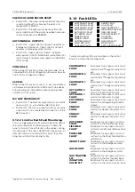
Note
Any circuits in Disabled or Test modes are
cleared to the normal mode after power to
the panel is lost.
Note
The I.S. configuration status is stored in
EEPROM and is not lost when power to the
panel is lost.
WARNING
The use of capacitors on intrinsically
safe zones is dangerous and carries a
risk of explosion. I.S. zones require a
3.9 kΩ EOL resistor.
Note
If a SLU is configured to use the panel circuits
for switch monitoring, the SLU will automati-
cally be configured as an indication only unit.
The panel must therefore be configured for a
type 1 SLU at the corresponding address.


