background image

F

IRE

F

LEX

®

  N

2


B

LAST

®


Integrated Fire Protection System 

O

WNER

'

O

PERATION 

&


M

AINTENANCE 

M

ANUAL


FM-076B-0-6A 

Page 1 of 25


1. GENERAL 

The 

F

IRE

F

LEX

®


N

2

 Blast

®


integrated system consists of a 

self contained preaction automatic sprinkler system 
combined with a Nitrogen Generator, factory-assembled in 
a single cabinet.  All the components necessary for both 
extinguishing systems are integrated. 

1.1  APPLICABLE STANDARDS 

In addition to being fabricated under stringent ISO-9001 
manufacturing and quality control procedures, your 

F

IRE

F

LEX 

N

2

 Blast

®

 complies with the following standards: 

NFPA-13 Sprinkler Systems 

NFPA-70 National Electrical Code 

NFPA-72 Fire Alarm Systems 

Before the installation, the contractor installing the unit shall 
also be familiar with the following documents and 
standards: 

Applicable Local & State Building Codes 

Any additional requirements of the Local Authority Having 
Jurisdiction 

1.2  LISTINGS & APPROVALS 

In addition to being fabricated under tight ISO-9001 
manufacturing and quality control procedures, the 

F

IRE

F

LEX

®


N

2

 Blast

®

 uses UL/ULC and/or FM approved 

components. 

WARNING

 Any unauthorized modification or addition made 

on-site to a factory built unit will void the unit's warranty.  
Consult your nearest FireFlex Systems Authorized Distributor 
before proceeding with such modifications or additions. 

1.3  ENVIRONMENT 

F

IRE

F

LEX

®


N

2

 Blast

®®


unit shall be installed in a dry and 

clean location.  Verify that all equipments are properly 
heated and protected to prevent freezing and physical 
damage. 

The unit and its components must be kept free of foreign 
matter, freezing conditions, corrosive atmospheres, 
contaminated water supplies, and any condition that could 
impair its operation or damage the components. 

1.4  GENERAL DESCRIPTION 

The 

F

IRE

F

LEX

®


N

2

 Blast

®

 integrates the same type of 

preaction automatic sprinklers system as found in the 
renowned 

F

IRE

F

LEX

 Systems


T

OTAL

P

AC

®

3

 using top 

quality 

Viking Corporation

 components and the deluge 

valve model  F-1. 

The Nitrogen generator is a 

N

2

 Blast

®

 Type 1 

FPS-250 

or FPS-750 system, made by 

South-Tek Systems.


The 

N

2

 Blast

®

 FPS-250 and FPS-750 designed & 

manufactured by South-Tek Systems provide an 
economical, precise means of generating high purity 
Nitrogen.  Since air is comprised of ~79% N

2

 we simply 

and cost-effectively separate the N

2

 from the air. 

Nitrogen is an inert gas (non-combustible) and widely 
used in thousands of industries along with Fire 
Protection Systems.  The N

2

 is “generated” by means of 

the air compressor pushing air into the simple, safe 
membrane element, which in turn mechanically 
separates N

2

 molecules from other molecules found 

within air.   

The 

F

IRE

F

LEX

®


N

2

 Blast

®


cabinet is of the free-standing 

type and is made of robust 14 gauge steel with a 
rustproof fire red paint finish, polyester powder coated 
and oven baked on a phosphate base.  Each cabinet is 
provided with two locked doors, reducing space 
requirements for ease of installation and maintenance. 


Summary of Contents for N2 BLAST

Page 1: ...FireFlex Preaction Double Interlocked Electric Pneumatic Release Self Contained Fire Protection Systems O M Manual FM 076B 0 6A 2020 The Leader in Nitrogen Generation Technology...

Page 2: ...al is prohibited While all reasonable efforts have been taken in the preparation of this manual to assure its accuracy FIREFLEX Systems Inc assumes no liability resulting from any errors or omissions...

Page 3: ...r 3 2 5 BlastOff Leak Detection System 3 2 6 N2 Blast AutoPurge System 3 2 7 Nitrogen generator 3 Air Pressure Maintenance Device 3 3 PREACTION SYSTEM 4 3 1 DESCRIPTION 4 3 2 CONFIGURATION 4 3 3 RELEA...

Page 4: ...mpressor Style A 16 5 2 Air Pressure Maintenance Device Style B 17 5 3 OPERATION 18 5 3 1 Air supply Style A 18 5 3 2 Air supply Style B 18 5 4 MAINTENANCE AND INSPECTION 19 5 4 1 Air supply style A 1...

Page 5: ...be installed in a dry and clean location Verify that all equipments are properly heated and protected to prevent freezing and physical damage The unit and its components must be kept free of foreign...

Page 6: ...Key alike locks on all cabinet doors Manufactured under ISO 9001 quality control procedures 1 6 CONFIGURATION FIREFLEX N2 Blast Preaction systems are built around the Viking trim using straight throug...

Page 7: ...t in larger Fire Protection Systems those requiring more Nitrogen to compensate for the NFPA acceptable leak rate 2 5 BlastOff Leak Detection System Unless the leak rate is catastrophic the supervisor...

Page 8: ...1724 kPa working water pressure max and is available in the following diameters f 1 40 mm f 2 50 mm f 3 80 mm f 4 100 mm 3 3 RELEASE Release trim for the electric pneumatic operated double interlocke...

Page 9: ...If the system does not operate as it should make the necessary corrections according to manuals issued or consult your distributor or FIREFLEX Systems Inc 8 Make sure that building owner or a delegate...

Page 10: ...ntrol valve D1 8 When full flow develops from the drain test valve B6 CLOSE the drain test valve and verify that there is no flow from the drip check valve B7 when the plunger is pushed 9 FULLY OPEN t...

Page 11: ...S To take system out of service WARNING Placing a system out of service may eliminate the fire protection capabilities of the system Prior to proceeding notify all Authorities Having Jurisdiction Cons...

Page 12: ...l come on and the Operating green light will illuminate until the N2 storage tank pressure reaches maximum approximately 75 Psi and the compressor shuts off Reset the remote release control panel Sole...

Page 13: ...the main drain valve D3 2 Verify that low air supervisory operate within pressure setting from table 5 3 3 Close the Inspectors test valve or the main drain valve D3 4 Establish recommended air press...

Page 14: ...efer any noted problems or deficiencies to authorized service personnel for correction 4 8 5 Semi annual inspection 1 Check main water supply control valve D1 switch upon movement of the hand wheel 2...

Page 15: ...6B 0 6A Page 11 of 25 Figure 4 1 P ID Tank Provided with brackets and Strap Riser towards the nozzles N2 Blast Compressor Air Maintenance Device s AMD s Supplied by Fireflex Preaction Compressor Preac...

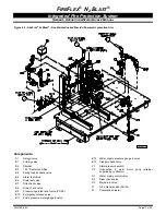
Page 16: ...Integrated Fire Protection System OWNER S OPERATION MAINTENANCE MANUAL Page 12 of25 FM 076B 0 6A Figure 4 2 FIREFLEX N2 Blast shown without doors FM 06LM 0 1A 4 FM 06LM 0 1A 4 See figures 4 3 4 4 for...

Page 17: ...icted orifice B4 Spring loaded check valve B5 Alarm test valve B6 Drain test valve B7 Drip check valve B8 Drain check valve B9 Pressure operated relief valve PORV B10 Emergency release valve B11 Prime...

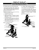
Page 18: ...076B 0 6A Figure 4 4 FIREFLEX N2 Blast storage tank FM 06LM 0 1A 1 FM 06LM 0 1A 1 N1 Nitrogen generator air pressure maintenance device N2 Nitrogen generator air pressure maintenance device control v...

Page 19: ...system refer to chapter 4 6 PLACING THE SYSTEM BACK IN SERVICE AFTER OPERATION 5 FULLY OPEN the system shut off valve D4 Reset the remote releasing control panel Figure 4 7 Shut off valve option Main...

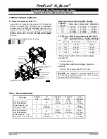
Page 20: ...30Vac 60Hz 220Vac 50Hz 1 6 5 0 Amp 2 5 Amp 1 3 Amp 1 3 7 4 Amp 3 7 Amp 2 5 Amp 1 2 10 0 Amp 5 0 Amp 4 0 Amp 1 18 0 Amp 9 0 Amp 6 0 Amp 115 230 Vac 60Hz air compressor selection Table H P CFM 40 PSI Sy...

Page 21: ...ry nitrogen cylinders and piped to the air inlet port of the unit Air supply style B provides an Air Pressure Maintenance Device APMD trim factory mounted in the FIREFLEX N2 Blast cabinets E16 This se...

Page 22: ...eplace the cover on the switch E2 Note Do not turn the cut out adjustment screw middle screw all the way down in one shot Proceed by steps Use the same method turning the cut out adjustment screw COUN...

Page 23: ...e pump to run hotter and results in longer operating cycles N2 Blast Nitrogen generator Intake filters The N2 BLAST FPS 250 and FPS 750 utilize three different filters The filters must be changed out...

Page 24: ...d air flow through the APMD E5 will allow Determine the appropriate pressure to be maintained in the system refer to table 5 The APMD E5 should be checked after installation or repair and adjusted as...

Page 25: ...section replaced by Dehydrator option A when used TO OPTIONAL ACCELERATOR plugged when not used FM 061H 0 118B 1 CONTRACTOR S HYDROSTATIC TEST PORT system side 2 E2 E11 TO DRAIN COLLECTOR Air option c...

Page 26: ...RATOR plugged when not used E4 plugged with SureFire trim FM 061H 0 119B 1 CONTRACTOR S HYDROSTATIC TEST PORT system side E5 TO SPRINKLER RISER E8 Note The external air supply must be restricted to in...

Page 27: ...dicated on figure 6 1 6 2 REMOTE CONTROLED FIREFLEX N2 Blast Without integrated releasing control panel For application with FIREFLEX N2 Blast unit provided without integrated releasing control panel...

Page 28: ...OUTLET TBB TBA TBC CONTROL PANEL except for Remote Controlled Unit SPRINKLER RISER SCH 40 GROOVED OUTLET T R G M D P F S FM 06LM 0 2A OPTIONAL SHUT OFF VALVE CONTROL PANEL TBA TBB TBC N Q C A B Syste...

Page 29: ...RING OF INPUT POWER SOURCE Branch circuit for air compressor shall not be the same as the control panel power source 6 7 8 9 10 11 C NO NC MAIN VALVE C NO NC SHUT OFF VALVE Contact provided for connec...

Page 30: ...other damages suffered by anyone There are no other warranties expressed or implied with regard to the products other than those contained herein Some jurisdictions may not allow limitations on how l...

Reviews: