REV. C Page 13
Firegear Outdoors All Weather Ignition System (AWS)
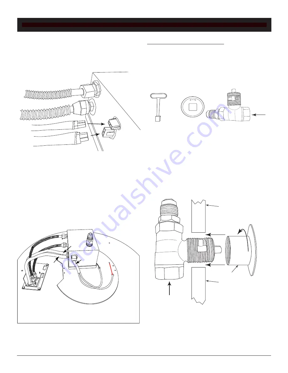
The pilot assembly has two pilots inside the perforated
hood. One uses a flared fitting to connect to the valve box
an the other pilot uses a compression fitting. Secure both
fittings to the valve box using a
9
/
16
” open-end wrench for
the flared fitting and a ½” open end for the compression
fittings. See Fig. 17.
Fig. 17
Connecting pilot assembly to valve box.
Install the 2-PIN connectors (items #1 & #2 in Fig. 18) from
the pilot assembly into the valve box, located next to the
pilot assembly fittings. Ensure the connector locks into
position. See Fig. 17.
Note:
Connectors are two different
types to prevent incorrect connection.
Plug the red and black power supply wire, item #3, in
Fig. 18 into the 2-PIN connector on the side of the valve
box. Note the red sleeve on the positive wire when
attaching the power supply.
Fig. 18
Shows three 2-PIN connectors installed into valve
box and the power supply wires attached to valve box.
The key valve contents: (1) key valve, (1) 12-inch key and
(1) flange. See Fig. 19. The valve requires a 1¼” round
clearance hole in the non-combustible enclosure wall. See
the instructions supplied with the key valve for more
specific details.
Note:
Be sure to leak test all fittings before
operating.
Primary Gas
Supply
ON
OFF
INSTALLING MANUAL KEY VALVE
Fig. 19
Key valve components
1
2
3
Key Valve Flange
Non-Combustible
Wall Material
Non-Combustible
Wall Material
Key Valve
Primary Gas
Supply
Fig. 20
Key valve components
Depending on the enclosure being used, the key valve can
be installed in various methods. The flange threads onto
the valve as shown and comes with one fitting to attach the
flex gas line that is supplied with the fire pit. The
primary gas line fitting (not supplied) is left up to the
plumber to supply depending on the connection needed for
the installation See Fig. 20.
INSTALLING VALVE KIT TO BURNER PAN


