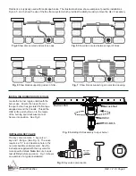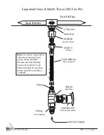
Round Flat Disc
REV. 1-7-19 Page 15
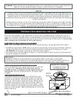
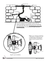
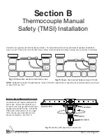
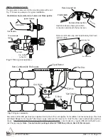
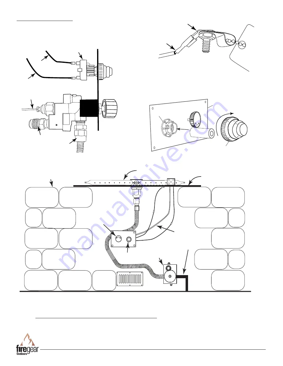
Fig. 17
TMSI typical installation.
Gas Outlet
to Fire Pit
Gas Inlet
Thermocouple
Lead
PIEZO48WH
PIEZO23WH
Ignitor Module
+
-
AAA
Plastic Nut
Red Button Cap
Mounting Plate
Illustration shows side view of valve and Piezo ignitor.
Remove red button cap and install battery into Piezo
ignitor module.
Piezo Ground Tab
Ratin
g Pla
te
Bottom of Burner Pan
PIEZO48WH
Illustration above shows ground tab
connection underneath the burner pan.
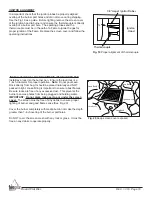
INSTALLING GAS VALVE
The gas valve is secured into the mounting plate with a nut.
Fig. 17 shows an example of a typical installation.
Gas Supply
Flat Disc
Non-Combustible Enclousure
E-Stop
Spur Burner
OFF
Gas Valve
TC Wire
Piezo
PUSH TO STOP
TURN TO START
OFF
0.5
HOURS
1
1.5
2
2.5
Gas valve and flexible gas lines are supplied; E-stop shut-off is not supplies, but available in accessories page. Flex lines
with flared fittings do not require Teflon tape or pipe compound. Ensure not to “kink” the flex lines to allow better gas flow
of gas. The illustration above is only a guide for the gas connection. Local codes may require different methods to con-
nect the gas supply.
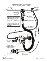
Note: See optional mounting method of TMSI face plate on back of this manual.
Fig. 18
Typical installation.


