18
Firegear Outdoors® Key West™ Series
INSTALLATION
9.
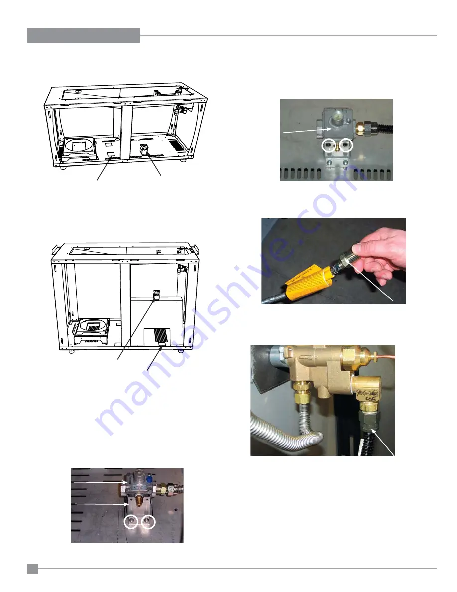
Remove connector from end of fl ex line.
Remove
connector
Diagram 10
11
. Bring gas to appliance. The connector removed in previous steps
can be used on the inlet side of the regulator.
12
. Check all gas connections (at valve, regulator, and LP outlet) under
normal operating pressure, for leaks, with soapy water.
NOTE
: If soap bubbles, this would indicate a gas leak.
13.
Check inlet and outlet pressures.
10
. Connect fl ex line to valve fi tting.
Connect fl ex line
to valve
Diagram 11
NOTE:
Top bracket to sit over top of lower bracket.
Attach supplied "MAX. 0.5 PSI" sticker to top bracket.
Regulator
Regulator
Bracket
6.
Remove LP tank and LP hose from valve.
7
. Install regulator bracket onto unit base with 2 screws. Connect fl ex
line to regulator—position regulator onto bracket.
8
. Secure regulator in position with top bracket - secure with 2 screws.
Diagram 8
Top
Bracket
Diagram 9
Location to install
regulator
Location to install
regulator
Access for
Hard line
(knockout)
Access for
Hard line
(knockout)
Diagram 6
Diagram 7
Coffee table unit only
Island and Cocktail table units
Summary of Contents for KWBH-2
Page 6: ...6 Firegear Outdoors Key West Series DIMENSIONS UNIT DIMENSIONS DINING HEIGHT ...
Page 7: ...Firegear Outdoors Key West Series 7 DIMENSIONS UNIT DIMENSIONS BAR HEIGHT ...
Page 35: ...Firegear Outdoors Key West Series 35 PARTS LIST DINING AND BAR HEIGHT ...
Page 36: ...36 Firegear Outdoors Key West Series PARTS LIST COFFEE HEIGHT ...
Page 37: ...Firegear Outdoors Key West Series 37 NOTES ...


