background image

REV. C     Page 6

Drop in Pan - Match Throw Fire Pits

IMPORTANT

Installation of Natural or LP gas should be done by a qualified installer, service agency or gas supplier.

This appliance must be isolated from the gas supply piping system by closing its manual shutoff valve during any 

pressure testing of the gas supply piping system at test pressures equal to or less than ½” psig (3.5kPa)

Description:

  These fire pits are designed to be installed into a non-combustible enclosure.  They are a “drop-in” style 

system to make installation quick and convenient.  Media (not supplied) is required inside the burner pan for operation 

(See page 9).  

WARNING: 

Proper clearances from combustible materials must be maintained from all sides, top and bottom of this 

appliance.  Use the specifications listed on pages 4 and 5 for proper clearance to combustibles. 

Firegear Outdoors fire pits are constructed and tested to follow the rigid ANSI standards for gas appliances and 

manufactured safely providing dependable and certified products.  If these fire pits are not installed according to the 

installation manual (i.e. not providing ventilation, not providing proper drainage, installing fire pits below grade or 

modifying the existing products from a normal installation) Firegear Outdoors cannot be responsible if the product does 

not operate as designed.  

Modifying the fire pit directly out of the carton will void the warranty and nullify the product listing it was certified for. 

Before you consider creating your own custom design with a certified product ensure you contact Firegear Outdoors to 

consult the installation before proceeding.   If you move forward and modify a product without consulting, Firegear 

Outdoors cannot be responsible if the product does not operate as designed.  

PREPARING A NON-COMBUSTIBLE STRUCTURE

The fire pit can be installed on a flat, stable surface, away from any combustible materials. Install fire pit on any level, 

outdoor non-combustible, flat stable surface or a combustible floor according to the clearances specified in this manual. 

NOTE

: Do not place fire pit directly on grass, dirt, or rocks this may prevent proper ventilation.  

Ensure proper water 

drainage is also incorporated into the fire pit enclosure.

HARD PIPING TO FIRE PIT WITHOUT GAS PROXIMITY

NOTE:

  Refer to the NFPA54 (National Fuel Gas Code) for proper pipe sizing.  See gas line sizing chart on page 8 as a 

reference.

1. Turn 

OFF

 gas supply system. 

NOTE

: All gas connections (except for brass to brass) require the following. Clean pipe 

threads using either a wire brush or steel wool. Apply pipe sealant to the fittings before making any connection. 

BE CAREFUL!

 Ensure all gas connections are snug, but do not over tighten!

2. Extend the gas supply system using minimum of ¾” black iron pipe or an approved flexible gas line from existing 

house supply.  This can be accomplished by teeing off or tapping into a gas line connection. Install necessary pipe for the       

distance required and then install a manual shut-off valve at the exterior house wall. If pipe is to pass through a foundation 

or house wall, make sure to re-seal the area around the pipe with weather sealant.

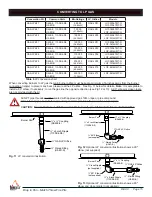
3. The primary gas shut-off (not supplied) will require a ⅜” male flared fitting to enable connection of the stainless steel 

flex gas line supplied with the fire pit (see Fig. 7 page 10).

Summary of Contents for LOF-2406TMT-N

Page 1: ...e Pit with H Burner LOF 7216HMT N P 72 x 16 Fire Pit with H Burner LOF 8416HMT N P 84 x 16 Fire Pit with H Burner LOF 9616HMT N P 96 x 16 Fire Pit with H Burner MODELS H Burner T Burner DO NOT DISCARD THIS MANUAL HAS IMPORTANT OPERATING AND MAINTENANCE INSTRUCTIONS LEAVE WITH THE HOMEOWNER MODEL SERIAL PN 90134 Model N Natural P Propane Description LOF 2406TMT N P 24 x 6 Fire Pit with T Burner LOF...

Page 2: ...e department DANGER WARNING Do not store or us gasoline or other flammable vapors and liquids in the vicinity of this or other appliances Any LP cylinder not connected for use shall not be stored in the vicinity of this or other appliances WARNING Do not leave unattended during use Do not use for cooking Follow all gas leak procedures in this manual prior to operation WARNING Improper installation...

Page 3: ... pop outside the fireplace WE HIGHLY RECOMMEND COVERING ALL FIRE FEATURES WHEN NOT IN USE The use of a cover can lessen the impact of thermal spalling however heavy rains high humidity and the presence of moisture may still cause the media to pop ALWAYS USE CAUTION WHEN USING THE FIRE FEATURE Extra caution should be taken when lighting a fireplace when heavy rains high humidity and moisture are pr...

Page 4: ...mm 8 203mm 36 914mm 120 3048mm 18 457mm LOF 8416HMT N LOF 8416HMT P 84 x 16 2133 x 406mm 86 x 18 2197 x 469mm 81 x 10 2057x 254mm 85 x 17 2159 x 330mm 8 203mm 8 203mm 120 3048mm 18 457mm LOF 9616HMT N LOF 9616HMT P 96 x 16 2438 x 406mm 98 x 18 2501 x 469mm 93 x 10 2362 x 254mm 97 x 17 2463 x 330mm 8 203mm 8 203mm 120 3048mm 18 457mm Fig 1 H style burner pan specifications SPECIFICATIONS Models N N...

Page 5: ...mm LOF 8406TMT N LOF 8406TMT P 84 x 6 2133 x 152mm 86 x 8 2197 x 215mm 81 2057mm 85 x 7 2159 x 178mm 8 203mm 36 914mm 120 3048mm 18 457mm LOF 9606TMT N LOF 9606TMT P 96 x 6 2438 x 152mm 98 x 8 2501 x 215mm 93 2362mm 97 x 7 2463 x 178mm 8 203mm 36 914mm 120 3048mm 18 457mm SPECIFICATIONS Models N NG P LP NG Orifice Btu Ratings LP Orifice LOF 2406TMT N LOF 2406TMT P 34 50 000 14 65kW 47 LOF 3006TMT ...

Page 6: ...regear Outdoors to consult the installation before proceeding If you move forward and modify a product without consulting Firegear Outdoors cannot be responsible if the product does not operate as designed PREPARING A NON COMBUSTIBLE STRUCTURE The fire pit can be installed on a flat stable surface away from any combustible materials Install fire pit on any level outdoor non combustible flat stable...

Page 7: ... the fire pit into the non combustible enclosure Refer to Table 1 dimension A 4 Follow the local code requirements for the gas type being used This fire pit should be installed in accordance with local codes and ordinances or in the absence of local codes with the latest National Fuel Gas Code ANSI Z223 1 NFPA54 or CSA B149 1 Natural and Propane Installation Code in Canada 5 Fire pits create high ...

Page 8: ...required for the amount of BTU s for a new gas line installations If you are using an existing gas line you must take into consideration the existing gas line capacities to ensure you will have proper pressure This chart is for reference only we recommend you consult with a Licensed Plumber Gas Fitter or NFPA54 National Fuel Gas Code current edition for more details Length of Pipe in Feet 1 2 3 4 ...

Page 9: ... details Note Be sure to leak test all fitting before operation Fig 5 shows an example of a typical installation Primary Gas Supply O N O F F Fig 6 Key valve components INSTALLATION OF LAVA ROCK MEDIA INTO BURNER PAN Install lava rock media into the burner pan Ensure the media is a minimum of 1 inch diameter for proper operation Note Do not pour Lava Rock directly from bag Media should be placed n...

Page 10: ...n Combustible Wall Material Non Combustible Wall Material Key Valve Key Valve Side View Det a i l Note A 1 x 2 black iron or galvanized coupler nipple not supplied can be used as a spacer between the manual valve and the valve flange to add additional support to hold the manual key valve in place Key Valve Flange Non Combustible Wall Material Non Combustible Wall Material Key Valve Black Iron Nipp...

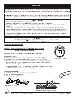
Page 11: ... before each use of the appliance 6 Temporary storage of this appliance indoors is permissible only if it has been disconnected from its fuel supply Natural or L P gas line WARNING 1 This appliance is hot when operated and can cause severe burns if contacted 2 Do not burn any solid fuels in this appliance LIGHTING INSTRUCTIONS Key Fig 9 Inserting Key into Valve O N O F F Fig 8 Key Valve Face Butan...

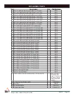
Page 12: ...REV C Page 12 Drop in Pan Match Throw Fire Pits O N O F F TMSI REPLACEMENT PARTS 1 2 6 7 5 9 10 Drawings not to scale 4 3 8 11 ...

Page 13: ...Only use with 21 T burner 1 78032 3 30 x 6 LT Burner Pan Only use with 27 T burner 1 78033 3 36 x 6 LT Burner Pan Only use with 33 T burner 1 78034 3 48 x 6 LT Burner Pan Only use with 45 T burner 1 78035 3 60 x 6 LT Burner Pan Only use with 57 T burner 1 78036 3 72 x 6 LT Burner Pan Only use with 69 T burner 1 78037 3 84 x 6 LT Burner Pan Only use with 81 T burner 1 78058 3 96 x 6 LT Burner Pan O...

Page 14: ... much media overtop of burner it can inhibit gas from flowing 4 Check gas pressure 5 Ensure thermocouple is correct height Tip of thermocouple should be fully engulfed by flame and approximately 1 35mm to 1 45mm from base of bracket 6 Check thermocouple voltage Minimum voltage to operate system is 12 14mV Low flame 1 Ensure the base media is at least 1 inch in diameter and top media is no more tha...

Page 15: ...orifice must be kept a minimum of 6 inches away from the burner connection nipple to prevent any back pressure at the LP orifice See Fig 11 below for details Note It is acceptable to install a 90 elbow if necessary to run the gas line the opposite direction see Fig 12 or 13 A 90 elbow or close nipple are not provided with the kit All NPT pipe threads must be sealed with approved gas Teflon tape or...

Page 16: ...YEAR WARRANTY REFRACTORY GAS LOG SETS FIVE 5 YEAR WARRANTY READY TO FINISH ANF FIRE PIT ENCLOSURES FIVE 5 YEAR WARRANTY SKYTECH MANUACFTURED OPTIONAL CONTROLS OUTDOOR FIREPLACE KALEA BAY LIFETIME WARRANTY CONSTRUCTION AND MANUFACTURER DEFECTS LIFETIME WARRANTY STAINLESS STEEL COMPONENTS FIVE 5 YEAR WARRANTY GAS VALVE PILOT ASSEMBLY POWER SUPPLY CONTROLS FIVE 5 YEAR WARRANTY SKYTECH MANUACFTURED OP...

Page 17: ...PLACE KALEA BAY LIFETIME WARRANTY CONSTRUCTION AND MANUFACTURER DEFECTS LIFETIME WARRANTY STAINLESS STEEL COMPONENTS TWO 2 YEAR WARRANTY GAS VALVE PILOT ASSEMBLY POWER SUPPLY CONTROLS TWO 2 YEAR WARRANTY SKYTECH MANUACFTURED OPTIONAL CONTROLS SANCTUARY SERIES GFRC FIRE FEATURES THREE 3 YEAR WARRANTY GFRC STRUCTURE REFER TO THE APPROPRIATE BURNER SYSTEM FOR WARRANTY WARRANTY COVERS MANUFACTURING DE...

Page 18: ...epair the defect on warranty parts to and from the factory will be the responsibility of the owner We will not be responsible for labor charges and or damage incurred in installation repair and replacement Firegear is not responsible for Issues related to gas or electrical installation The Limited Warranty is voided if not assembled installed and operated as intended This Limited Warranty does not...

Page 19: ...epair the defect on warranty parts to and from the factory will be the responsibility of the owner We will not be responsible for labor charges and or damage incurred in installation repair and replacement Firegear is not responsible for Issues related to gas or electrical installation The Limited Warranty is voided if not assembled installed and operated as intended This Limited Warranty does not...

Page 20: ...ncidental or consequential damages so this limitation or exclusion may not apply to you We do not authorize any person or company to assume for it any other obligation or liability in connection with the sale installation use removal return or replacement of its equipment and or such representation are binding Firegear Outdoors 17322 Gothard Street Huntington Beach CA 92647 www firegearoutdoors co...

Page 21: ...REV C Page 21 Drop in Pan Match Throw Fire Pits NOTES ...

Page 22: ..._____ 2 Serial Number ___________________________ 3 How long is the gas line run Nat Gas ____ LP Gas ____ 4 What size is gas line _____ 5 Inlet Gas Pressure _____WC Manifold Gas Pressure _____ WC 6 What type of media are you using __________________ 7 Review the troubleshooting section in the installation manual 8 What are the symptoms Please be prepared to explain 9 Be prepared to send photos to ...

Reviews: