27
NFOD42 Gas Fireplace
INSTALLATION
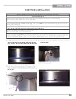
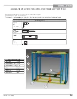
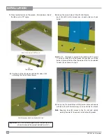
6)
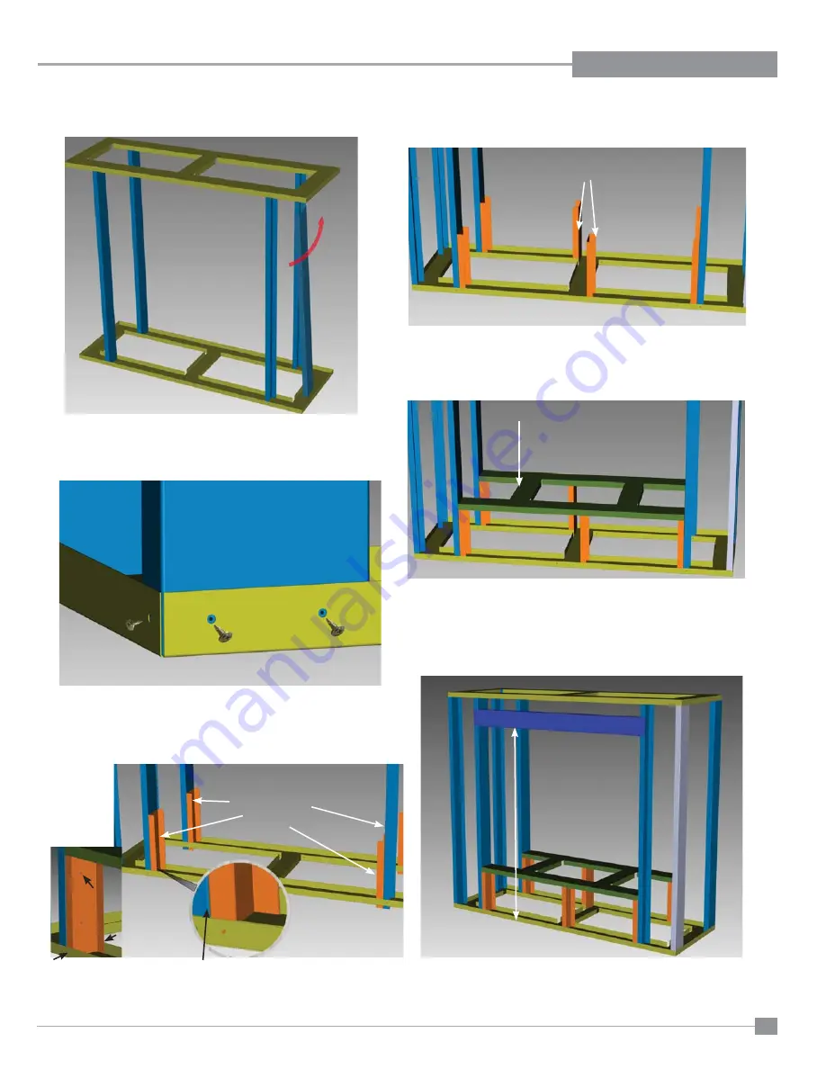
Manoeuvre remaining (B) pieces and position in each corner
of the frame - fl at side facing out - see 2 diagrams below.
7)
LIne up screw holes on top / bottom (A) with each (B)- secure
with 3 wafer screws each on top and bottom - 6 screws in
total for each outer (B) (3 top- 3 bottom).
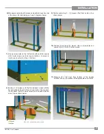
8)
Position 4 - (C) pieces with the fl at side back to back with the
fl at side of each inner Part B as shown below. Secure each
(C) to bottom (A) with 3 wafer screws (one on each side and
one at top as shown below.
9)
Position remaining 2 - (C) pieces offset from center rib as
shown below.
10)
Position (D) on top of (C) pieces - line up screw holes and
secure (D) to (C) with 12 wafer screws.
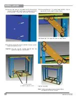
11)
Measure 44-11/16" from fl
oor (bottom of the header
location) line up (E) (header) with appropriate screw holes.
(C)Screw
locations
44-11/16"
(E)
(D)
(C)
(B)+ (C) - fl at sides back to back
(C
)
(B)
(A)


