background image


CoolSmart TV 

PB 24CF, PB 36CF, 564 25K, 564 35K, 3615HO 

(sku# 98900778) 


Page 9 of 37 

17602034- 12/13/21 

© Travis Industries, Inc.  

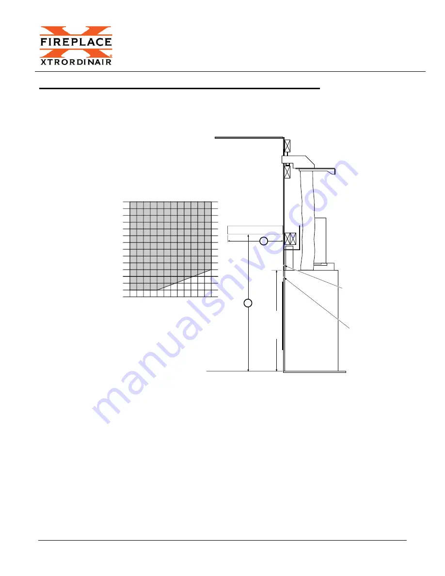
PB 24CF & PB 36CF - Reduced Mantel Height 

When using this kit, disregard the combustible mantel requirements in the manual and follow the requirements 
shown to the right.  If you wish to place a TV above the mantel, it must meet the following requirements: 

  Minimum 1” air gap behind TV to wall. 

  The mantel must extend 2” in front of the TV and 1” to both sides. 


b

Maximum Mantel Depth (b) With 

CoolSmart TV Kit

Mantel Height 

Above Base (a) With 

CoolSmart TV Kit

46" (1169mm)

0" (0mm)

1" (25mm)

2" (51mm)

8" (203mm)

7" (178mm)

6" (152mm)

5" (127mm)

4" (102mm)

3" (76mm)

9" (229mm)

10" (254mm)

11" (279mm)

12" (305mm)

45" (1143mm)
44" (1118mm)
43" (1093mm)
42" (1067mm)
41" (1042mm)
40" (1016mm)

47" (1194mm)

39" (991mm)

37" (941mm)

38" (966mm)

36" (916mm)
35" (890mm)
34" (864mm)

Non-Combustible 
Facing Only

ProBuilder 

24CF & 36CF 

Fireplace

Min.

35"

890mm

a

Combustible Facing 
(Min. 35" 890mm above 
base of fireplace)

Summary of Contents for 564 25K

Page 1: ...24CF PB 36CF Installation Overview 3 PB 24CF PB 36CF Installation Requirements 4 PB 24CF Framing the Chase 5 PB 36CF Framing the Chase 6 PB 24CF PB 36CF Fireplace Preparation 7 PB 36CF ONLY Convection Air Deflectors 8 PB 24CF PB 36CF Reduced Mantel Height 9 564 25K Installation Overview 10 564 25K Installation Requirements 11 564 25K Framing the Chase 12 564 25K Fireplace Preparation 13 564 25K Re...

Page 2: ...Grill and Manifold Dimensions The grill may be installed over the facing to provide an aesthetic opening for the convection outlet 2 8 32 x 1 1 2 screws attach the trim to the upper manifold This allows variable thickness of finish material Dimensions a b c d e 35 7 8 912mm 2 7 8 74mm 1 1 4 32mm 34 7 8 886mm 1 3 4 45mm ...

Page 3: ...and a recessed cavity above the fireplace When using this kit disregard the standard framing dimensions and follow the framing instructions for the CoolSmart kit When used on the PB234 CF PB36 CF this kit allows for the non combustible facing height to be reduced See illustration below for details Min 1 1 2 39mm Max 120 3048mm Min 73 3 4 1690mm Non Combustible Facing Only Ceiling ProBuilder 24CF 3...

Page 4: ...CoolSmart TV PB 24CF PB 36CF 564 25K 564 35K 3615HO sku 98900778 Page 4 of 37 17602034 12 13 21 Travis Industries Inc PB 24CF PB 36CF Installation Requirements ...

Page 5: ...r the manifold is installed It is used to secure the nailing brackets on the fireplace to the framing It also provides support for the facing above the fireplace This framing is not required in some cases you may use other methods to secure the nailing brackets and facing 3 3 4 96mm Upper Manifold Framing Lower Manifold Framing 8 1 2 216mm Bottom of Upper Manifold Framing Braces for Manifold Suppo...

Page 6: ...e When using this kit disregard the framing dimensions in the manual and follow the framing instructions shown below Max 120 3048mm Min 73 3 4 1874mm 3 3 4 96mm Upper Manifold Framing Lower Manifold Framing 8 1 2 216mm Bottom of Upper Manifold Framing Braces for Manifold Support Brackets 37 3 8 950mm 41 1042mm 15 1 4 388mm 26 1 2 674mm PB36CF ...

Page 7: ...ip the tab on the knockouts Press on the far side away from the tap to pop the edge of the knockout up 2 Grab on to the knockout with pliers and bend it back and forth until the remaining tabs break free Discard the knock out plate 3 Under each knock out plate you will find a cover plate held in place with 2 screws Use a nut driver or drill with an extension to remove the 2 screws Reach in and rem...

Page 8: ...oth air openings After removing the cover plates install the deflectors as shown below 4 Insert a starter collar into each of the 2 holes that were uncovered in the previous step and bend the tabs to secure the starter collar to the fireplace Seal the joints with silicone caulk or aluminum U L 181A P tape 5 Install the fireplace into the framed chase Note how the deflector points downward to the r...

Page 9: ...nd TV to wall The mantel must extend 2 in front of the TV and 1 to both sides b Maximum Mantel Depth b With CoolSmart TV Kit Mantel Height Above Base a With CoolSmart TV Kit 46 1169mm 0 0 m m 1 2 5 m m 2 5 1 m m 8 2 0 3 m m 7 1 7 8 m m 6 1 5 2 m m 5 1 2 7 m m 4 1 0 2 m m 3 7 6 m m 9 2 2 9 m m 1 0 2 5 4 m m 1 1 2 7 9 m m 1 2 3 0 5 m m 45 1143mm 44 1118mm 43 1093mm 42 1067mm 41 1042mm 40 1016mm 47 1...

Page 10: ...is kit allows for reduced clearances to televisions and a recessed cavity above the fireplace When using this kit disregard the standard framing dimensions and follow the framing instructions for the CoolSmart kit 564 25K CleanFace 564 25K Standard a 41 3 8 1051mm 41 3 8 1051mm b 33 1 8 842mm 30 1 4 769mm Optional Recessed Pocket Combustible Facing Allowed 564 25K Fireplace CF or Std Non Combustib...

Page 11: ...CoolSmart TV PB 24CF PB 36CF 564 25K 564 35K 3615HO sku 98900778 Page 11 of 37 17602034 12 13 21 Travis Industries Inc 564 25K Installation Requirements ...

Page 12: ...in the manual and follow the framing instructions shown below 564 25K Standard 564 25K CleanFace a 37 3 4 959mm 38 3 4 985mm b 17 1 2 445mm 19 3 8 493mm Flush 18 7 8 480mm Extended c 37 1 4 947mm 37 1 4 947mm Max 120 3048mm Min 70 7 8 1801mm 3 3 4 96mm Upper Manifold Framing Lower Manifold Framing 8 1 2 216mm Bottom of Upper Manifold Framing Braces for Manifold Support Brackets 26 1 2 674mm a b c ...

Page 13: ...ace Preparation 1 Remove the knockouts from the top of the fireplace Use snips or diagonal cutters to snip the tab on the knockouts Press on the far side away from the top to pop the edge of the knockout up 2 Grab on to the knockout with pliers and bend it back and forth until the remaining tabs break free Discard the knock out plate ...

Page 14: ...ill find a cover plate held in place with 2 screws Use a nut driver or drill with an extension to remove the 2 screws Reach in and remove the cover plate You may discard the plate 4 You will need to remove a third cover plate on each side Remove the 2 screws holding the cover plate in place Reach in and remove the cover plate You may discard this plate ...

Page 15: ...eps on the other end of the fireplace 6 Insert a starter collar into each of the 2 holes that were uncovered in the previous step and bend the tabs to secure the starter collar to the fireplace Seal the joints with silicone caulk or aluminum U L 181A P tape 7 Install the fireplace into the framed chase See section Installation in the manual ...

Page 16: ...t disregard the combustible mantel requirements in the manual and follow the requirements shown to the right If you wish to place a TV above the mantel it must meet the following requirements Minimum 1 air gap behind TV to wall The mantel must extend 2 in front of the TV and 1 to both sides Max 12 305mm Min 33 1 4 844mm 564 25K Fireplace CF or Std Combustible Mantel ...

Page 17: ...is kit allows for reduced clearances to televisions and a recessed cavity above the fireplace When using this kit disregard the standard framing dimensions and follow the framing instructions for the CoolSmart kit 564 35K CleanFace 564 35K Standard a 47 3 8 1203mm 47 3 8 1203mm b 33 1 8 842mm 30 1 4 769mm Optional Recessed Pocket Combustible Facing Allowed 564 35k Fireplace CF or Std Non Combustib...

Page 18: ...CoolSmart TV PB 24CF PB 36CF 564 25K 564 35K 3615HO sku 98900778 Page 18 of 37 17602034 12 13 21 Travis Industries Inc 564 35K Installation Requirements ...

Page 19: ...in the manual and follow the framing instructions shown below 564 35K Standard 564 35K CleanFace a 37 3 4 959mm 38 3 4 985mm b 17 1 2 445mm 19 3 8 493mm Flush 18 7 8 480mm Extended c 37 1 4 947mm 37 1 4 947mm 3 3 4 Upper Manifold Framing Lower Manifold Framing 8 1 2 Bottom of Upper Manifold Framing Braces for Manifold Support Brackets 26 1 2 674mm 216mm 96mm Max 120 3048mm Min 76 7 8 1953mm a b c ...

Page 20: ...ace Preparation 7 Remove the knockouts from the top of the fireplace Use snips or diagonal cutters to snip the tab on the knockouts Press on the far side away from the top to pop the edge of the knockout up 8 Grab on to the knockout with pliers and bend it back and forth until the remaining tabs break free Discard the knock out plate ...

Page 21: ...ill find a cover plate held in place with 2 screws Use a nut driver or drill with an extension to remove the 2 screws Reach in and remove the cover plate You may discard the plate 10 You will need to remove a third cover plate on each side Remove the 2 screws holding the cover plate in place Reach in and remove the cover plate You may discard this plate ...

Page 22: ...eps on the other end of the fireplace 12 Insert a starter collar into each of the 2 holes that were uncovered in the previous step and bend the tabs to secure the starter collar to the fireplace Seal the joints with silicone caulk or aluminum U L 181A P tape 7 Install the fireplace into the framed chase See section Installation in the manual ...

Page 23: ...t disregard the combustible mantel requirements in the manual and follow the requirements shown to the right If you wish to place a TV above the mantel it must meet the following requirements Minimum 1 air gap behind TV to wall The mantel must extend 2 in front of the TV and 1 to both sides Max 12 305mm Min 33 1 4 844mm 564 35K Fireplace CF or Std Combustible Mantel ...

Page 24: ... of this kit allows for reduced clearances to televisions and a recessed cavity above the fireplace When using this kit disregard the standard framing dimensions and follow the framing instructions for the CoolSmart kit Min 1 1 2 39mm Max 120 3048mm Min 67 1 4 1709mm Ceiling Optional Recessed Pocket Min 38 5 8 982mm above base of fireplace Min 38 5 8 982mm 982mm Max 3 1 8 80mm Television 12 1 2 Mi...

Page 25: ...CoolSmart TV PB 24CF PB 36CF 564 25K 564 35K 3615HO sku 98900778 Page 25 of 37 17602034 12 13 21 Travis Industries Inc 3615 HO Installation Requirements ...

Page 26: ... is required from all four sides of the tile stop on the fireplace If no trim is being used the airspace is not required see below for details NOTE The maximum facing depth combustible non combustible facing is 1 1 4 Any facing that extends farther than 1 1 4 must meet mantel clearances WARNING The front of the appliance is subject to high temperatures which may cause discoloration and or material...

Page 27: ...replace The drywall can contact the top of the fireplace top Use a nut driver to remove the 8 screws that secure the header assembly to the top of the fireplace Slide the header assembly back Align the header assembly with the second set of holes in the fireplace Reattach the assembly to the fireplace use the screws removed in the first step WARNING For flush installations combustible facing can t...

Page 28: ...d after the fireplace is put into position It is used to provide support for the facing above the fireplace and nailing brackets 3 3 4 96mm Upper Manifold Framing Lower Manifold Framing 8 1 2 216mm Bottom of Upper Manifold Framing Braces for Manifold Support Brackets 24 1 2 674mm 17 432mm Flush Install 37 5 8 956mm 40 3 4 1036mm Max 120 3048mm Min 67 1 4 1709mm 3615 CoolSmart Framing ...

Page 29: ...l framing members included with the fireplace 3615 and 4415 have 3 and 6015 has 4 Remove the screws that secure the sheetrock backer L shaped metal bracket secured to the metal header of the unit and discard the backer see first illustration below Bend the pipe heat shield back and forth until it snaps off of the metal header Discard the heat shield see middle and right illustrations below 3615 44...

Page 30: ...x attachment points on the top of the fireplace Not removing all of the cover plates can create hazardous conditions First Layer Remove the 2 5 knockouts leave the square cover plates in place Use snips or diagonal cutters to snip the tab on the knockouts Press on the far side away from the tab to pop the edge of the knockout up Grab on to the knockout with pliers and bend it back and forth until ...

Page 31: ...ockout plates you will see another set of knockouts Remove these knockouts using the same technique described above Third final Layer Under the second layer of knockout plates you will find cover plates held in place with 2 screws Use a nut driver or drill with an extension to remove the 2 screws Reach in and remove the cover plate You may discard the plates ...

Page 32: ... Inc Install the starter collars onto the fireplace see below Install the fireplace into the framed chase See section Installation in the manual Starter Collar Bend the tabs on the bottom of the starter collar up to lock it in place S i l i c o n e Use silicone to seal the starter collar to the top of the fireplace ...

Page 33: ... 1 to both sides b Maximum Mantel Depth b With CoolSmart TV Kit Mantel Height Above Base a With CoolSmart TV Kit 46 1169mm 0 0 m m 1 2 5 m m 2 5 1 m m 8 2 0 3 m m 7 1 7 8 m m 6 1 5 2 m m 5 1 2 7 m m 4 1 0 2 m m 3 7 6 m m 9 2 2 9 m m 1 0 2 5 4 m m 1 1 2 7 9 m m 1 2 3 0 5 m m 45 1143mm 44 1118mm 43 1093mm 42 1067mm 41 1042mm 40 1016mm 47 1194mm 39 991mm 37 941mm 38 966mm 36 916mm Non Combustible Fac...

Page 34: ... horizontal framing member at the desired height parallel to the header Install a second horizontal framing member 3 3 4 above the first These two framing members will support the upper convection manifold in the following steps 4 Hold the upper convection manifold with the outlet facing the back of the framing members installed in the previous step Tilt the outlet of the manifold downward until t...

Page 35: ... of the convection manifold Leave the screws loose so the brackets can be positioned to the back of the chase Secure the brackets to the chase using screws not included Tighten the screws securing the brackets to the manifold 7 Insert a starter collar into each of the 2 holes that were uncovered in the previous step and bend the tabs to secure the starter collar to the fireplace Seal the joints wi...

Page 36: ...oints with silicone caulk or aluminum U L 181A P tape 9 Cover the face of the fireplace and the outlet of the manifold to ensure no construction debris or sheetrock dust enters the unit 10 Once all finish work is complete around the outlet of the manifold install the outlet grill assembly using the two included screws one at each end The grill assembly will overlap finish material up to 1 1 2 thic...

Page 37: ... a minimum sideways vent you may transition the 5 flex vent to a ridged nominal 6 oval pipe to get past the obstruction Transition back to the 5 round flex and continue to the manifold The adapters and ridged pipe should be factory ovalized not field ovalized NOTE All clearances to combustibles must be maintained 5 5 5 3 7 3 4 3 7 3 4 5 Flex to fireplace 5 round to 6 oval adapter 5 round to 6 oval...

Page 38: ... a minimum of 1 3 8 35mm below the top edge of the lower framing for the manifold approx 2 5 8 67mm from the bottom of the manifold outlet The distance from the front of the manifold opening to the inside surface of the front of the valance must be a minimum of 6 153mm The front wall of the valance can be a maximum of 6 153mm tall see illustration below If the valance has an end cap the inner surf...

Reviews: