background image

Service Manual 0-2692

11

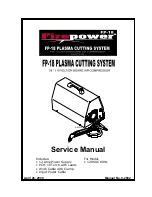
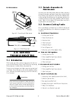
Firepower FP-18 Plasma Cutter

7 .  Faulty Control PCB  or Relay

CAUTION

 Be sure torch is directed away from people or haz-
ards. A pilot arc may start!

a.  Push the test button on the side of the Relay. If

the Compressor starts and the torch operates,
the PCB or Relay has most likely failed.

The PCB  can be isolated by removing the push
on connectors from the Relay coil and measur-
ing the relay coil with an ohmmeter. If the coil
measures between 50 - 100ohms, the Relay is
good and the PCB should be replaced.

If the Compressor runs intermittently and arc-
ing can be seen in the Relay case while the torch
switch is held on, the relay contacts are worn
and the Relay should be replaced.

F.  Power OK, fan runs, compressor runs

intermittently, Relay Case shows
arcing when the torch switch is held
on.

1.  Faulty Relay.

a.  If the Compressor runs intermittently and arc-

ing can be seen in the Relay Case while the torch
switch is held on, the relay contacts are worn
and the Relay should be replaced.

G.  Power OK, fan runs, compressor starts

then shuts down as soon as the torch
switch is pressed.

1.  Shorted, damaged, or incorrect torch parts.

a.  Check that all torch parts are in good condition

and designed for use in the PCH-10 torch.

2.  Faulty (open) Voltage Divider Resistor.

a.  The voltage divider is the top Resistor.  Discon-

nect the push-on connectors and measure the
Resistor with an ohmmeter. It should read 1K
ohms.  If measurement is not 1K ohms, replace
Resistor.

3.  Shorted Bridge Rectifier (BR1).

a.  Probable if a loud hum or buzz is heard from

the main transformer after the Relay actuates.

If hum or buzzing noise exists, replace Bridge
Rectifier. (replace lower Bridge Rectifier, clos-
est to Chassis).

H.  Power OK, fan runs, compressor runs,

no pilot or cutting arc with the torch
switch pressed.

1.  Worn, contaminated, or incorrect torch parts.

a.  Check that all torch parts are in good condition

and designed for use in the PCH-10 torch.  Re-
place worn parts as necessary.

2.  Parts not assembled correctly.

a.  Reassemble torch parts.

3.  Damaged torch or leads.

a.  Check per subsection 3.6, Torch and Leads

Troubleshooting.

4.  Faulty Control PCB.

a.  Listen for a faint, sharp clicking noise, at about

3-4 clicks/second from the Ferrite Core Assem-
bly.  If nothing is heard, the PCB should be re-
placed.

5.  Faulty (open) Pilot Resistor.

a.  The Pilot Resistor is mounted closest to the chas-

sis. Disconnect the the push on connectors and
measure the resistor with an ohmmeter.  It
should read 0.5 ohms (essentially a short).

6.  AC input too low.

a.  If the AC line is below about 105vac, the torch

may not always start.  Try an outlet on a differ-
ent branch circuit.

7.  Faulty Ferrite/Transformer Assembly.

a.  The Ferrite Transformer Assembly is used to

generate a high voltage pulse to establish the
pilot arc. Troubleshooting is limited to visual
inspection. The two primary connections and
two secondary connections should be checked
for general integrity and snug fit onto the push
on connectors.  The Transformer Assembly it-
self should be free of large ferrite chips and
cracks along the core.

I.  Torch pilots but does not cut well.

1.  AC input power too low.

a.  Use shortest service from AC outlet to breaker

panel as possible or larger gauge extension cord.

2.  Work cable not attached.

a.  Check work cable connection.

3.  Restricted air flow.

a.  Check lead for kinks or pinching restricting air

flow.

Summary of Contents for FP-18

Page 1: ...Manual No 0 2692 April 26 2000 Service Manual A 02032 Includes 12 Amp Power Supply PCH 10 Torch with Leads Work Cable with Clamp Input Power Cable For Model 120VAC 60Hz ...

Page 2: ......

Page 3: ...rial Park No 2 West Lebanon New Hampshire USA 03784 603 298 5711 Copyright 1999 by Thermal Dynamics Corporation All rights reserved Reproduction of this work in whole or in part without written permission of the publisher is prohibited The publisher does not assume and hereby disclaims any liabil ity to any party for any loss or damage caused by any error or omission in the Firepower FP 18 Plasma ...

Page 4: ...Troubleshooting Guide 9 3 6 Torch Leads Troubleshooting 12 4 0 REPAIRS REPLACEMENT PROCEDURES 12 4 1 General Information 12 4 2 Removing Cover Handle 13 4 3 Torch Head Assembly Replacement 13 4 4 Torch Switch Only Replacement 14 4 5 Air Compressor Replacement 15 4 6 Capacitor Replacement 15 4 7 Control PC Board Replacement 16 4 8 Power Relay Replacement 16 4 9 ON OFF Power Switch Replacement 17 4 ...

Page 5: ...nic Cobalt Nickel Barium Copper Selenium Beryllium Lead Silver Cadmium Manganese Vanadium Always read the Material Safety Data Sheets MSDS that should be supplied with the material you are using These MSDSs will give you the information regarding the kind and amount of fumes and gases that may be dangerous to your health For information on how to test for fumes and gases in your work place refer t...

Page 6: ... Stan dards Institute 1430 Broadway New York NY 10018 6 ANSI Standard Z49 2 FIRE PREVENTION IN THE USE OF CUTTING AND WELDING PROCESSES obtainable from American National Standards Institute 1430 Broadway New York NY 10018 7 AWS Standard A6 0 WELDING AND CUTTING CONTAIN ERS WHICH HAVE HELD COMBUSTIBLES obtainable from American Welding Society 550 N W LeJeune Rd Miami FL 33126 8 NFPAStandard 51 OXYG...

Page 7: ... nettoyage chlorés Eliminez toute source de telle fumée CHOC ELECTRIQUE Les chocs électriques peuvent blesser ou même tuer Le procédé au jet de plasma requiert et produit de l énergie électrique haute tension Cette énergie électrique peut produire des chocs graves voire mortels pour l opérateur et les autres personnes sur le lieu de travail Ne touchez jamais une pièce sous tension ou vive portez d...

Page 8: ...ROTECTRICES disponible auprès de l American National Standards Institute 1430 Broadway New York NY 10018 6 Norme ANSI Z49 2 PRÉVENTION DES INCENDIES LORS DE L EMPLOI DE PROCÉDÉS DE COUPE ET DE SOUDAGE disponible auprès de l American National Standards Institute 1430 Broadway New York NY 10018 7 Norme A6 0 de l Association Américaine du Soudage AWS LE SOUDAGE ET LA COUPE DE CONTENEURS AYANT RENFERM...

Page 9: ...A Canadian StandardsAssociation standard C22 2 number 60 forArc welding equipment UL Underwriters Laboratory rating 94VO flammability testing for all printed circuit boards used ISO IEC 60974 1 BS 638 PT10 EN 60 974 1 applicable to welding equipment and associated accessories Extensive product design verification is conducted at the manufacturing facility as part of the routine design and manufact...

Page 10: ...y goods covered by or furnished by Firepower whether arising out of contract negligence strict tort or under any warranty or otherwise shall not except as expressly provided herein exceed the price of the goods upon which such liability is based THIS WARRANTY BECOMES INVALID IF REPLACEMENT PARTS OR ACCESSORIES ARE USED WHICH MAY IMPAIR THE SAFETY OR PERFORMANCE OF ANY FIREPOWER PRODUCT THIS WARRAN...

Page 11: ...on in this edition is particularly applicable to the Troubleshooting and Repair of the equipment and is intended for use by properly trained Service Technicians familiar with this equipment Read this manual and the Firepower FP 18 Plasma Cut ter Operating Manual 0 2691 thoroughly A complete understanding of the capabilities and functions of the equipment will assure obtaining the performance for w...

Page 12: ...the inspection and maintenance procedures which should be performed at periodic intervals Routine Maintenance ensures optimum performance of equipment and can pre vent the user from encountering problems with this equip ment Refer to that manual for instructions on power supply and torch maintenance 3 3 Common Cutting Faults Poor or lackluster performance can often be improved by slight modificati...

Page 13: ...oting One of the features of this plasma cutter is the con stant DC pilot This means the plasma arc is always on either as a pilot arc or a cutting arc resulting in a very smooth forgiving system This also means that the torch tip will wear fairly rapidly if you pilot for an extended time or cut with too great a standoff es sentially switching from a transferred cutting arc back to the constant DC...

Page 14: ...uit breaker or fuse opens after the power switch is switched on go to step D2 If the circuit breaker or fuse is okay replace Fan 2 Faulty Transformer Assembly or Capacitor a With the Fan still disconnected disconnect two leads from the transformer that are connected to the Capacitor then apply power If the circuit breaker or fuse opens after power is applied the Capacitor is shorted Replace Capaci...

Page 15: ... the Relay actuates If hum or buzzing noise exists replace Bridge Rectifier replace lower Bridge Rectifier clos est to Chassis H Power OK fan runs compressor runs no pilot or cutting arc with the torch switch pressed 1 Worn contaminated or incorrect torch parts a Check that all torch parts are in good condition and designed for use in the PCH 10 torch Re place worn parts as necessary 2 Parts not a...

Page 16: ...between the electrode seat negative and the brass threads of the torch assembly Infinite resis tance no continuity should be found If there is con tinuity between the two remove the torch head from the lead and check the torch head separately B Checking Torch Lead If the torch head assembly is okay check the torch lead by measuring the resistance between the positive pilot lead connector and the n...

Page 17: ... light cutting gloves when changing torch parts just after operating the FP 18 System To Remove Torch Head Assembly NOTE Refer to Figure 4 1 for parts identification 1 Remove consumable parts from front end of torch 2 Remove six screws from torch handle assembly A 3 Remove both torch handle halves from the torch and leads assembly then complete the following a Disconnect positive pilot lead connec...

Page 18: ...nstalling Torch Head Assembly 4 4 Torch Switch Only Replacement NOTE This procedure requires the following tools or equivalent screwdriver soldering iron Nokorde Flux WARNING Disconnect primary power to the system before dis assembling the torch leads or power supply 1 Remove consumable parts from front end of torch 2 Remove the six screws from the torch handle as sembly and remove torch and leads...

Page 19: ...n nut completely as there are small parts inside that could fall out 10 Connect the following as it pertains to your unit Rev C units or earlier Connect black wire from Compressor to faston splice wire 21 Connect red wire from Compressor to upper diode piggyback terminal Rev D units or earlier Connect black wire from Compressor to faston splice wire 29 Connect red wire from Compressor to upper dio...

Page 20: ...ting holes a Remove two 2 fastener plastic push ons from key slotted holes in corners of PC Board b Slide PC Board up or down to disengage then remove from unit B To Install Replacement PC Board 1 Install replacement key slotted PC Board by plac ing PC Board over standoffs and sliding Board down into position 2 Push a white fastener plastic push on into each keyhole just above standoffs to secure ...

Page 21: ...ay use screws instead of rivets 5 Install replacement Fan Refer to Figure 5 1 for proper Fan orientation or refer to the arrows marked on the Fan chassis NOTE Proper fan orientation is essential to ensure proper cooling of power supply parts 6 Install Compressor by reversing steps 1 3 keeping in mind the following a Position wire connector L4 so that it runs along side the Transformer NOT across t...

Page 22: ... Remove two Ferrite Core Assembly screws which hold the Transformer Ferrite Core Assembly in position Remove Transformer Ferrite Core As sembly from unit 5 Install replacement Transformer Ferrite Core As sembly by reversing steps 1 4 keeping in mind the following a Pull L4 through loose tie wrap if available b Position wire connector L4 so that it runs along side the Transformer NOT across the top...

Page 23: ... your unit Description Catalog A Complete Systems Includes Power Supply PCH 10 70 Torch with Leads Spare Consumable Parts Input Power Cord and Work Cable FIREPOWER 120V 60Hz PCH 10 1445 0047 B Torch Leads Only Includes Torch Leads 90 Nylon Air Compressor Fitting Torch Leads alone are not replaceable PCH 10 70 w 20 ft 6 m Leads 2 1020 ...

Page 24: ... 1 Fan 120V 60Hz Fan 115V 50 60Hz 95 115CFM 8 3209 8 1 Compressor Air 12VDC 0 5 CFM 9 0010 9 1 Resistor 0 5ohm 55 watt 10 3 16 Faston 9 0011 10 1 Resistor 1Kohm 55 watt 5 3 16 Faston 9 0012 11 1 Work Cable 15 ft 4 57 m w Red Handles 9 0013 12 1 Input Power Cable 6 5 ft min 2 m 16 3 w molded plug 9 0014 13 1 ON OFF Switch ON OFF Switch DPST 125V 15A RED NEON 5 Prongs 9 0015 ON OFF Switch DPST 125V ...

Page 25: ...Torch Leads A Screw 6 32 x 3 3 4 Lg Phil Pan Hd Zinc B 6 32 Regular Nylon Lock Nut Zinc Plated C 5 16 18 x 1 3 4 Unc Cap Socket Head Bolt D 10 32 x 5 Pph Swageform Stl Zn Parker Kalon E Screw Black 6 32 x 1 2 Pph Swageform Steel F 10 32 Kepnut w Star Washer Mild Steel Air Flow Direction HARDWARE QTY 2 2 2 4 2 2 NOTE Replacement hardware can be purchased locally F F E E B B D D D C C A A 11 12 To r...

Page 26: ...arts Item Qty Description Catalog 1 1 PCH 10 70 Torch HeadAssembly 9 0016 2 1 Torch Handle Only 9 0019 3 1 Torch Switch 9 1058 4 1 Standard Electrode 1445 0016 5 1 PCH 10 Tip 1445 0031 6 1 Gas Distributor 1445 0017 7 1 Shield Cup 1445 0018 8 1 Torch Head Split Holders PCH 10 70 9 6259 9 1 PIP Parts In Place WireAssembly 9 6290 10 1 O Ring 8 0533 11 1 Torch Switch Button 8 4256 12 2 Torch Switch Bu...

Page 27: ...1 Clearance Strain Relief Torch Lead Faston Connector Red Connect to Bottom Resistor 2 Pin Connectors Torch Lead Faston Connector to CD Coil 90 White Nylon Fitting Brass Torch Lead Fitting A 02009 Nylon Nut Front Panel Hole Location Note Do not remove strain relief from torch lead APPENDIX I LEADS CONNECTIONS ...

Page 28: ...LK CD PRIMARY CD PWR CIRCUIT E6 E5 E1 E2 SPK1 350V Spark Gap LOGIC CIRCUIT 0 5 55 watt 1K 55 watt 22 3 watt W O R K T O R C H PILOT RED Sleeved 1 4 7 10 11 12 13 16 17 14 15 18 PIP Pin TORCH SWITCH CD PCB Shield Cup 1 4 7 10 11 12 13 16 17 14 15 18 21 22 5 6 20 19 20 19 11 29 8 7 7A 3 4 1 10 26 24 150µƒ 450v 50 5 watt 2 L1 27 43 L4 1A 1 23 4700µƒ 120 VAC 120 µƒ 180 VAC A 02345 NOTE Use this diagra...

Page 29: ...Service Manual 0 2692 25 Firepower FP 18 Plasma Cutter ...

Page 30: ...Firepower FP 18 Plasma Cutter 26 Service Manual 0 2692 APPENDIX III INTERCONNECTING DIAGRAM A 02361 ...

Page 31: ...Service Manual 0 2692 27 Firepower FP 18 Plasma Cutter NOTE Use this diagram for all rev D or later units Check the data tag on the unit for rev level A 02361 ...

Page 32: ......

Reviews: