


Firepower FP-18 Plasma Cutter
16
Service Manual 0-2692
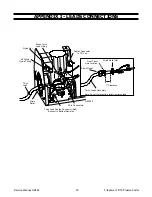
4.7 Control PC Board
Replacement
The FIREPOWER Plasma Cutter has been manufactured
using one of two styles of PC Board Assemblies. The
Board will either have round mounting holes in the cor-
ners or key slotted mounting holes in the corners. Fol-
low procedures as they apply to your unit.
NOTES
It may be easier to remove the PC Board if the Ca-
pacitor is removed first.
All replacement PC Boards have key slotted holes.
WARNING
Disconnect primary power to the system before dis-
assembling the torch, leads, or power supply.
A. To Remove PC Board:
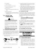
1. Remove cover/handle from unit per subsection 4.2.
2. Remove Capacitor (optional) per subsection 4.6.
3. Note all wiring connections and locations to the
PC Board.
4. Disconnect all wire connections to the PC Board,
removing any tie wraps where necessary.
5. Remove PC Board from unit by completing the fol-
lowing, as it applies to your unit:
PC Board with round mounting holes:
a. Remove the two (2) metal "C" clips located on
the top two standoffs that secure the PC Board
to the unit.
b. Gently pry PC Board off the standoffs then re-
move the second set of metal "C" clips (2).
NOTE
In some cases, the PCB may be mounted on stand-
offs and secured with RTV over the ends. Remove
the RTV and then remove the PCB from the unit.
PC Board with key slotted mounting holes:
a. Remove two (2) fastener plastic push ons from
key slotted holes in corners of PC Board.
b. Slide PC Board up or down to disengage, then
remove from unit.
B. To Install Replacement PC Board:
1. Install replacement key slotted PC Board by plac-
ing PC Board over standoffs and sliding Board
down into position.
2. Push a white fastener plastic push on into each
keyhole (just above standoffs) to secure the PC
Board into position.
3. Reverse steps 1-4, keeping in mind the following:
a. Make sure J2 is not offset by one or more pins.
b. Install new tie wraps on wires connected to the
PC Board, as necessary.
4.8 Power Relay Replacement
NOTES
The Control PC Board must be moved out of the
way before the Power Relay can be replaced. (It may
be easier to move the Contrl PC Board if the Ca-
pacitor is removed first.)
Refer to subsection 4.1, General Information, for
information about wire harnesses.
WARNING
Disconnect primary power to the system before dis-
assembling the torch, leads, or power supply.
1. Remove cover/handle from unit per subsection 4.2.
2. Remove Capacitor (optional step) per instructions
in 4.6.
3. Remove PCB from standoffs per subsection 4.7.B.
4. Slide PC Board away from Relay.
5. Note all wiring connections and locations to the
Relay.
6. Remove wirings connected to Relay.
7. Slide Relay out from bracket, towards the center of
the unit.
8. Install replacement Relay, by reversing the above
steps, keeping in mind the following:
a. Position wire connector L4 so that it runs along
side the Transformer, NOT across the top of the
Transformer.
Summary of Contents for FP-18
Page 2: ......
Page 29: ...Service Manual 0 2692 25 Firepower FP 18 Plasma Cutter ...
Page 32: ......


