


Firepower FP-18 Plasma Cutter
18
Service Manual 0-2692
4. Disconnect all wiring connections to the Resistor(s).
5. Remove two nuts and washers securing Resistor to
chassis.
6. Remove Resistor(s).
7. Install replacement Resistor(s) by reversing steps
1-5, noting the following:
a. The top Resistor is 1K ohm and the bottom Re-
sistor is .5 ohm.
b. Tighten screws securely.
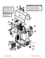
4.13 Transformer/Ferrite Core
Assembly Replacement
WARNINGS
Disconnect primary power at source before assem-
bling or disassembling the power supply.
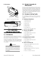
1. Remove cover/handle from unit per subsection 4.2.
2. Wire connections are as follows:
Connector
Location
L1
E6 on PCB
L2
E1 on PCB
L3
E2 on PCB
L4
Brass Torch
Lead Fitting
3. Disconnect wire connections. Pull L4 connector
through loose tie wrap if available.
4. Remove two Ferrite Core Assembly screws which
hold the Transformer/Ferrite Core Assembly in
position. Remove Transformer/Ferrite Core As-
sembly from unit.
5. Install replacement Transformer/Ferrite Core As-
sembly by reversing steps 1-4, keeping in mind
the following:
a. Pull L4 through loose tie wrap if available.
b. Position wire connector L4 so that it runs along
side the Transformer, NOT across the top of the
Transformer or near any metal parts.
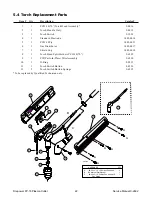
5.0 PARTS LIST
Order replacement parts by catalog number and complete
description of the part or assembly. Also include the
model and serial number of the torch. Address all in-
quiries to your authorized distributor or call toll free 1-
888-832-4250.
NOTE
Standard hardware has been used in this unit. Re-
placement hardware can be purchased locally.
5.1 Returns
If a product must be returned for service, contact your
authorized distributor. Items return to the manufacturer
without proper authorization will not be accepted.
Summary of Contents for FP-18
Page 2: ......
Page 29: ...Service Manual 0 2692 25 Firepower FP 18 Plasma Cutter ...
Page 32: ......


