6
The MIG gun on this unit is a “live” torch which is in the constant “ON” position.
Touching the torch to a grounded surface will produce and arc which could cause injury.
Please
USE CAUTION
when handling this unit.
ASSEMBLING THE WELDER
The following steps describe the assembly, installation, maintenance and operations of your new welder.
Avoid contacts with wires or parts.
DO NOT
work with the side panels
partially opened or removed completely from the power source.
The FP-90’s MIG gun torch is a “live” contact gun and is ALWAYS IN
THE POWER-ON POSITION. Wear Eye protection at all times when handling this
MIG gun.
Be sure that the welder’s elec-
trical power supply cord is not connected while performing this procedure.
Tools Required: Allen Wrench (metric)
1. Unpack the welder.
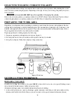
2. Assemble and install the plastic handle as shown in Figure 1.
3. Install MIG wire per instructions noted in section
“Installation of Welding Wire.”
4. Place the power source in a well ventilated area.
DONOT
obstruct the air intake and output vents. A reduced air flow
can cause a reduced duty cycle and damage internal compo-
nents.
5. Insure at least 6 feet of open space on the each side of the welder.
Connect the power supply cable to the correct receptacle, single-phase 120V(protected by slow blow fuses).
This equipment
MUST
be connected to ground.
WELDER INSTALLATION
POWER SOURCE CONNECTION
Power Requirements
This welder is designed to operate on a properly grounded 120 volt, 60 HZ, single-phase alternating current (AC)
power source fused with a 20 amp time-delayed fuse or circuit breaker. A qualified electrician should verify the
ACTU-
AL VOLTAGE
at the receptacle into which the welder will be plugged and confirm that the receptacle is properly
grounded. The use of the proper circuit size can eliminate the nuisance of circuit breaker tripping when welding.
DO NOT OPERATE THIS WELDER
if the ACTUAL power source voltage is less than 110 Volts AC or
greater than 132 Volts AC. Contact a qualified electrician if this problem exists. Improper performance and/or
damage to the welder will result if operated on inadequate or excessive power.
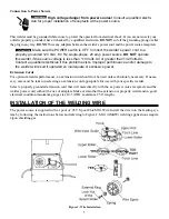
Figure 1: Handle Installation
Summary of Contents for FP-90
Page 2: ......
Page 27: ...23 Figure 21 FP 90...
Page 29: ...25 Figure 22 FP 90 Wiring Diagram...
Page 30: ...26...


