Firepower MST 140i
BASIC WELDING GUIDE
4-2
Manual 0-5338
The welding Gun should be held at an angle to the weld joint. (see Secondary Adjustment Variables below)
Hold the MIG Gun so that the welding seam is viewed at all times. Always wear the welding helmet with proper filter lenses
and use the proper safety equipment.
CAUTION
Do not pull the welding MIG Gun back when the arc is established. This will create excessive wire extension (stick-
out) and make a very poor weld.
The electrode wire is not energized until the MIG Gun trigger switch is depressed. The wire may therefore be placed on the
seam or joint prior to lowering the helmet.
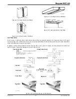
Butt & Horizontal Welds
Direction of
Travel
5° to 15°
Longitudinal
Angle
90°
Transverse
Angle
Art # A-08993
Figure 4-4
Horizontal Fillet Weld
Direction of
Travel
5° to 15°
Longitudinal Angle
30° to 60°
Transverse Angle
Art # A-08994
Figure 4-5
Vertical Fillet Welds
Art # A-08995
30° to 60°
Transverse
Angle
30° to 60°
Transverse
Angle
Direction of Travel
10°
Longitudinal Angle
10° to 20° Longitudinal
Angle
Figure 4-6
Overhead Weld
Art # A-08996
30° to 60°
Transverse Angle
Direction of Travel
5° to 15°
Longitudinal
Angle
Figure 4-7
Distance from the MIG Gun Nozzle to the Work Piece
The electrode wire stick-out from the MIG Gun nozzle should be between 3/8" (10mm) to 3/4" (20.0mm). This distance may
vary depending on the type of joint that is being welded.
Travel Speed
The speed at which the molten pool travels influences the width of the weld and penetration of the welding run.
MIG Welding Variables
Most of the welding done by all processes is on carbon steel. The items below describe the welding variables in short-arc
welding of 24 ga. (0.6mm) to ¼” (6.4mm) mild sheet or plate. The applied techniques and end results in the MIG process
are controlled by these variables.
Summary of Contents for MST 140i
Page 6: ...This Page Intentionally Blank ...
Page 76: ...Firepower MST 140i BASIC WELDING GUIDE 4 24 Manual 0 5338 This Page Intentionally Blank ...
Page 82: ...Firepower MST 140i KEY SPARE PARTS 6 2 Manual 0 5338 6 02 Power Source Art A 12518 31 ...
Page 86: ...Firepower MST 140i KEY SPARE PARTS 6 6 Manual 0 5338 This Page Intentionally Blank ...
Page 87: ...Firepower MST 140i Manual 0 5338 1 APPENDIX APPENDIX This Page Intentionally Blank ...
Page 89: ...Firepower MST 140i Manual 0 5338 3 APPENDIX Art A 12517 ...

