background image

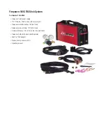
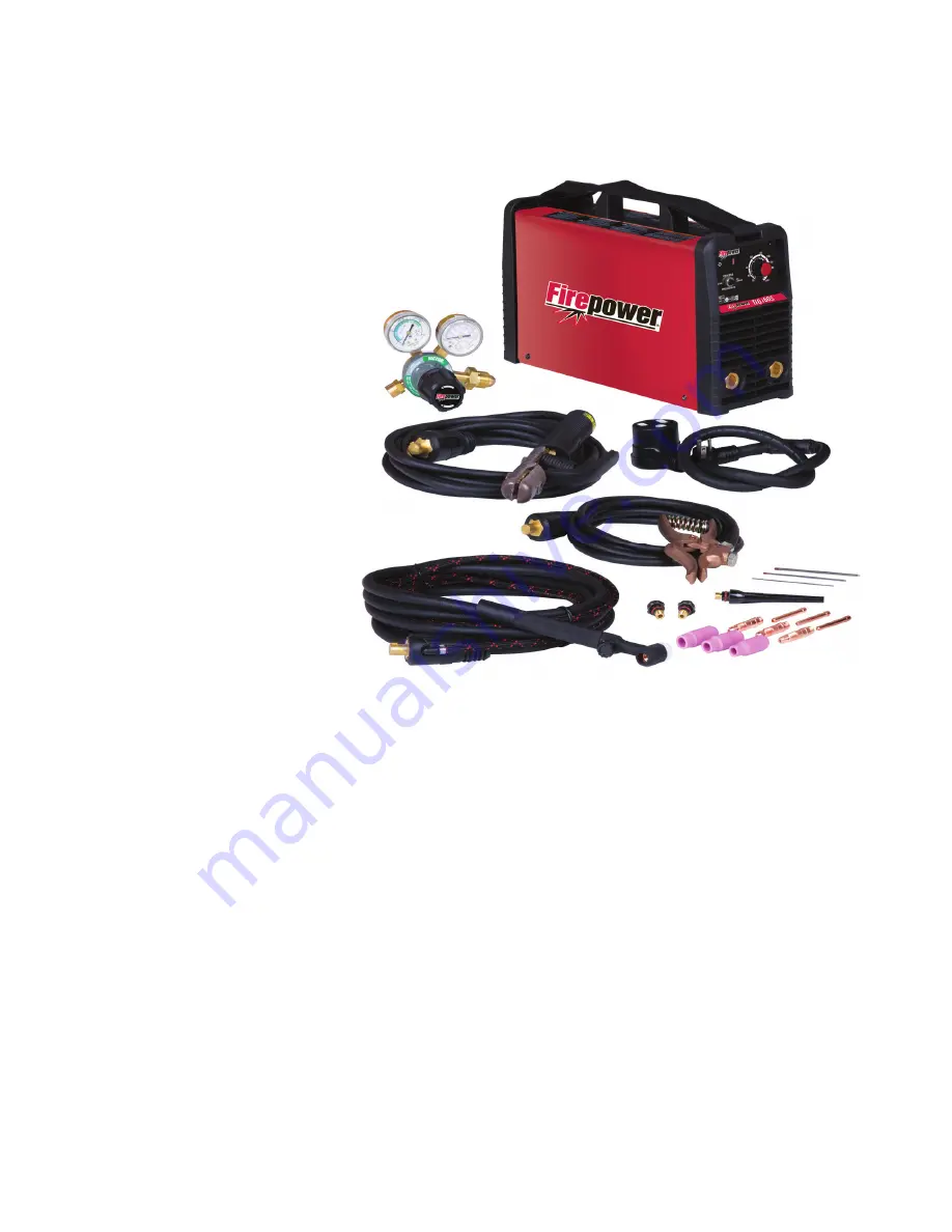
Firepower 160S TIG/Stick System

Part Number 1442-0036

•  Firepower 160S power supply 

•  17V TIG torch, 12.5ft (3.8m) with accessory kit

•  Firepower electrode holder, 13ft (4m) lead

•  Firepower ground clamp, 10ft (3.1m) lead

•  4 General Purpose 1/8” (3.2mm) dia. stick electrodes

•  Firepower CutSkill 2G Flowmeter/Regulator

•  230V to 115V adapter

•  Product family overview DVD

•  Operating manual

Summary of Contents for TIG 160S

Page 1: ...A 12705 A 12705 Operating Manual Firepower TIG 160S Inverter Arc Welder English Canadien Français Americas Español Revision AB Issue Date December 4 2014 Manual No 0 5369 www firepoweronline com 3163339 ...

Page 2: ...ur competition through market leading innovation and truly dependable products that will stand the test of time We strive to enhance your productivity efficiency and welding performance enabling you to excel in your craft We design products with the welder in mind delivering advanced features durability ease of use and ergonomic comfort Above all we are committed to a safer working environment wit...

Page 3: ...63017 USA www firepoweronline com Copyright 2014 by Victor Technologies Inc All rights reserved Reproduction of this work in whole or in part without written permission of the publisher is prohibited The publisher does not assume and hereby disclaims any liability to any party for any loss or damage caused by any error or omission in this Manual whether such error results from negligence accident ...

Page 4: ... Electromagnetic Compatibility 3 4 3 05 Setup for Welding 3 5 3 06 STICK SMAW Setup 3 6 3 07 LIFT TIG GTAW Setup 3 7 3 08 Firepower Flowmeter Regulator 3 8 3 09 Leak Testing the System 3 9 3 10 When You Finish Using the Flowmeter Regulator 3 10 3 11 Storage of the Flowmeter Regulator 3 10 SECTION 4 OPERATION 4 1 4 01 Front Panel 4 1 4 02 Welding Current Control Explanation 4 2 4 03 STICK SMAW Elec...

Page 5: ...1 4 22 Overcoming Distortion Effects 4 11 SECTION 5 SERVICE 5 1 5 01 Maintenance and Inspection 5 1 5 02 STICK SMAW Welding Problems 5 2 5 03 TIG Welding Problems 5 3 5 04 Power Source Problems 5 4 SECTION 6 replacement PARTS 6 1 6 01 Replacement Parts 6 1 APPENDIX 1 OPTIONS AND ACCESSORIES A 1 APPENDIX 2 SYSTEM SCHEMATIC A 2 Firepower LIMITED WARRANTY TERMS inside rear cover INTERNATIONAL CONTACT...

Page 6: ...y 17V TIG torch 12 5ft 3 8m with accessory kit Firepower electrode holder 13ft 4m lead Firepower ground clamp 10ft 3 1m lead 4 General Purpose 1 8 3 2mm dia stick electrodes Firepower CutSkill 2G Flowmeter Regulator 230V to 115V adapter Product family overview DVD Operating manual ...

Page 7: ...10 Ground the workpiece to a good electrical earth ground 11 Do not touch electrode while in contact with the work ground circuit 12 Use only well maintained equipment Repair or replace damaged parts at once 13 In confined spaces or damp locations do not use a welder with AC output unless it is equipped with a voltage reducer Use equipment with DC output 14 Wear a safety harness to prevent falling...

Page 8: ...aterial Safety Data Sheets MSDSs and the manufacturer s instruction for metals consumables coatings and cleaners AWS F2 2 2001 R2010 Adapted with permission of the American Welding Society AWS Miami Florida Guide for Shade Numbers Process Electrode Size in mm Arc Current Amperes Minimum Protective Shade Suggested Shade No Comfort Shielded Metal Arc Welding SMAW Less than 3 32 2 4 3 32 5 32 2 4 4 0...

Page 9: ... partition can cause fire on the hidden side 7 Do not weld on closed containers such as tanks or drums 8 Connect work cable to the work as close to the welding area as practical to prevent welding current from traveling long possibly unknown paths and causing electric shock and fire hazards 9 Do not use welder to thaw frozen pipes 10 Remove stick electrode from holder or cut off welding wire at co...

Page 10: ...ing servicing discon nect negative battery cable from battery 5 Keep hands hair loose clothing and tools away from moving parts 6 Reinstall panels or guards and close doors when servicing is finished and before starting engine WARNING SPARKS can cause BATTERY GASES TO EXPLODE BATTERY ACID can burn eyes and skin Batteries contain acid and generate explosive gases 1 Always wear a face shield when wo...

Page 11: ...ng or cutting operations must have fireproof tops 3 Use heat resistant shields or other approved material to protectnearbywallsorunprotectedflooringfromsparks and hot metal 4 Keep an approved fire extinguisher of the proper size and type in the work area Inspect it regularly to ensure that it is in proper working order Know how to use the fire extin guisher 5 Move combustible materials away from t...

Page 12: ...it over or expose it to excessive heat flames or sparks DO NOT strike it against other cylinders Contact your gas supplier or refer to CGA P 1 Safe Handling of Compressed Gases in Containers publication NOTE CGA P 1 publication is available by writing the Compressed Gas Association 4221 Walney Road 5th Floor Chantilly VA 20151 2923 2 Place the valve protection cap on the cylinder whenever mov ing ...

Page 13: ...402 Recommended Safe Practices for the Preparation for Welding and Cutting of Containers That Have Held Hazardous Substances American Welding Society Standard AWS F4 1 from American Welding Society 550 N W LeJeune Rd Miami FL 33126 National Electrical Code NFPA Standard 70 from National Fire Protection Association Batterymarch Park Quincy MA 02269 Safe Handling of Compressed Gases in Cylinders CGA...

Page 14: ...ve Positive Direct Current DC Protective Earth Ground Line Line Connection Auxiliary Power Receptacle Rating Auxiliary Power Art A 04130_AB 115V 15A t t1 t2 X IPM MPM t V Fuse Wire Feed Function Wire Feed Towards Workpiece With Output Voltage Off Preflow Time Postflow Time Spot Time Spot Weld Mode Continuous Weld Mode Press to initiate wirefeed and welding release to stop Purging Of Gas Inches Per...

Page 15: ...armonized standards EN 60974 10 2007 Arc Welding Equipment Part 10 Electromagnetic compatibility EMC requirements EN 60974 1 2012 Arc Welding Equipment Part 1 Welding power sources Classification The equipment described in this document is Class A and intended for industrial use Manufacturer s Authorized Representative Steve Ward V P Europe and General Manager Address Victor Technologies Internati...

Page 16: ... and intended for industrial use WARNING This Class A equipment is not intended for use in residential locations where the electrical power is provided by the public low voltage supply system There may be potential difficulties in ensuring electromagnetic compatibility in those locations due to conducted as well as radi ated disturbances ...

Page 17: ...e to shipping If there is any damage notify the carrier immediately to file a claim Furnish complete information concerning damage claims or shipping errors to the location in your area listed in the inside back cover of this manual Include all equipment identification numbers as described above along with a full description of the parts in error 2 04 Description This compact inverter welding mach...

Page 18: ...ty Cycle 35 100A 30 160A Welder Type Inverter Power Source Output Terminal Type Heavy Duty DinseTM 50 Classification Protection Class IP23S Standards CSA E60974 1 EN50199 Cooling Method Fan Cooled Dimensions and Weight Welding Power Source Mass 17 4 lb 7 9 kg Welding Power Source Dimensions Height x Width x Depth H 9 0 x W 5 3 x D 15 5 H230mm x W135mm x D393mm The recommended time delay fuse or ci...

Page 19: ...e skin resistance of the human body and the insulation properties of accessories Environments with increased hazard of electric shock do not include places where electrically conductive parts in the near vicinity of the operator which can cause increased hazard have been insulated This equipment can t be operated in rain or snow 3 02 Location Be sure to locate the welder according to the following...

Page 20: ...e how proper connections should be made and inspection required The line disconnect switch provides a safe and convenient means to completely remove all electrical power from the welding power supply whenever necessary to inspect or service the unit Do not connect an input WHITE or BLACK conductor to the ground terminal Do not connect the ground GREEN conductor to an input line terminal Refer to F...

Page 21: ...e charging for the input capacitors A relay in the Power Control Assembly PCA will turn on after the input capacitors have charged to operating voltage after approximately 5 seconds NOTE Damage to the PCA could occur if 253 VAC or higher is applied to the Primary Power Cable Model Primary Supply Lead Size Factory Fitted Minimum Primary Current Circuit Size Vin Amps Current Duty Cycle LIFT TIG GTAW...

Page 22: ...dditional protection measures The size of the surrounding area to be considered will depend on the structure of the building and other activities that are taking place The surrounding area may extend beyond the boundaries of the premises C Methods of Reducing Electromagnetic Emissions 1 Mains Supply Welding equipment should be connected to the mains supply according to the manufacturer s recommend...

Page 23: ...ening the entire welding installation may be considered for special applications 3 05 Setup for Welding NOTE Conventional operating procedures apply when using the Welding Power Source i e connect work lead directly to work piece and electrode lead is used to hold electrode Wide safety margins provided by the design ensure that the Welding Power Source will withstand short term overload without ad...

Page 24: ...rminal and the electrode holder cable to the positive output terminal NOTE This set up is known as DC Electrode Positive or reverse polarity Please consult with the stick electrode manufacturer for specific polarity recommendations 3 Connect the ground clamp to your workpiece 4 Plug the power cable into the appropriate outlet and turn the switch to the ON position The power L E D light should illu...

Page 25: ... torch cable to the negative output terminal NOTE This set up is known as Straight Polarity or DC Electrode Negative This is commonly used for DC TIG welding on most materials such as steel and stainless steel 3 Using a secured Argon cylinder slowly crack open then close the cylinder valve while standing off to the side of the valve This will remove any debris that may be around the valve regulato...

Page 26: ...than the maximum rated pressure stamped on the Flowmeter Regulator 2 The Flowmeter Regulator body will be stamped IN or HP at the inlet port Attach the inlet port to the system supply pressure connection 3 Wrap pipe threads with Teflon tape 1 1 2 to 2 turns to effect a seal If other sealants are used they must be compatible with the gas that will be used in the system 4 If gauges are to be attache...

Page 27: ... maximum pressure shows on the high pressure gauge Art A 09828 Figure 3 6 Open Cylinder Valve 10 On all cylinders except acetylene open the valve completely to seal the valve packing On gaugeless Flowmeter Regulators the indicator will register the cylinder contents open CAUTION Keep the cylinder valve wrench if one is required on the cylinder valve to turn off the cylinder quickly if necessary 12...

Page 28: ...linder valve 2 Open the valve on the downstream equipment This drains all pressure from the system 3 Close the valve on the downstream equipment 4 Turn the adjusting screw counterclockwise to release the ten sion on the adjusting spring 5 Check the gauges after a few minutes for verification that the cylinder valve is closed completely 3 11 Storage of the Flowmeter Regulator When the Flowmeter Reg...

Page 29: ... modes B Power On Indicator The Power ON Indicator illuminates when the ON OFF switch is in the ON position and the nominal mains volt age is present C Fault Indicator The welding power source is protected by a self resetting thermostat and over primary current protection devices Welding can not take place if the Fault Indicator lights up or lights up continuously Thermostat Protection If the Faul...

Page 30: ...TIG weld modes Nuisance tripping should not occur on a 50A 208 230V outlet for both STICK LIFT TIG Modes 15 Amp Outlet The mains power 15 Amp circuit breaker or fuse should not trip at this Weld Current value when STICK welding The environmental conditions that may cause the mains power 15 Amp circuit breaker or fuse to trip are a High ambient temperature b Worn parts in circuit breaker c Using an...

Page 31: ...the high rate of heat con ductivity of copper making pre heating of heavy sections necessary to give proper fusion of weld and base metal Types of Electrodes Arc Welding electrodes are classified into a number of groups depending on their applications There are a great number of electrodes used for specialized industrial purposes which are not of particular interest for everyday general work These...

Page 32: ...5 4 07 Tungsten Electrode Current Ranges Electrode Diameter DC Current 040 1 0mm 25 85 1 16 1 6mm 50 160 3 32 2 4mm 135 235 4 08 Shielding Gas Selection Alloy Shielding Gas Carbon Steel Welding Argon Stainless Steel Welding Argon Nickel Alloy Welding Argon Copper Welding Argon Titanium Welding Argon 4 09 Tungsten Electrode Types Electrode Type Ground Finish Welding Application Features Color Code ...

Page 33: ...70 40 60 1 16 1 6mm 1 16 1 6mm 15 CFH 7 LPM Butt Corner 70 90 50 70 Lap Filler 1 8 3 2mm 80 100 65 85 1 16 1 16mm 3 32 2 4mm 15CFH 7 LPM Butt Corner 90 115 90 110 Lap Filler 3 16 4 8mm 115 135 100 125 3 32 2 4mm 1 8 3 2mm 21CFH 10 LPM Butt Corner 140 165 125 150 Lap Filler 1 4 6 4mm 160 175 135 160 1 8 3 2mm 5 32 4 0mm 21CFH 10 LPM Butt Corner 170 200 160 180 Lap Filler 4 11 Arc Welding Practice T...

Page 34: ... this publication can be used in most positions i e they are suitable for welding in flat horizontal vertical and overhead positions Numerous applications call for welds to be made in positions intermediate between these Some of the common types of welds are shown in Figures 4 2 through 4 9 Art A 07687 Figure 4 3 Flat position down hand butt weld Art A 07688 Figure 4 4 Flat position gravity fillet...

Page 35: ...es being welded should be clean and free of rust scale dirt grease etc Slag should be removed from oxy cut surfaces Typical joint designs are shown in Figure 4 110 Gap varies from 1 16 1 6mm to 3 16 4 8mm depending on plate thickness Joint Open Square Butt 1 16 1 6mm max 1 6mm 1 16 Single Vee Butt Joint Not less than 70 Double Vee Butt Joint 1 16 1 6mm Lap Joint Tee Joints Fillet both sides of the...

Page 36: ... the work piece This is caused by making too heavy a contact with the work and failing to withdraw the electrode quickly enough A low amperage will accentuate it This freezing on of the tip may be overcome by scratching the electrode along the plate surface in the same way as a match is struck As soon as the arc is established maintain a 1 16 1 6mm to 1 8 3 2mm gap between the burning electrode en...

Page 37: ...t slag being trapped by the second run Subsequent runs are then deposited using either a weave technique or single beads laid down in the sequence shown in Figure 4 13 The width of weave should not be more than three times the core wire diameter of the electrode When the joint is completely filled the back is either machined ground or gouged out to remove slag which may be trapped in the root and ...

Page 38: ...d Art A 07702 Figure 4 18 Multi run vertical fillet weld Art A 07703 Figure 4 19 Examples of vertical fillet welds 2 Vertical Down The E7014 electrode makes welding in this position particularly easy Use a 1 8 3 2mm electrode at 120 amps The tip of the electrode is held in light contact with the work and the speed of downward travel is regulated so that the tip of the electrode just keeps ahead of...

Page 39: ... 4 20 Overhead fillet weld 4 20 Distortion Distortion in some degree is present in all forms of welding In many cases it is so small that it is barely perceptible but in other cases allowance has to be made before welding commences for the distortion that will subsequently occur The study of distortion is so complex that only a brief outline can be attempted hear 4 21 The Cause of Distortion Disto...

Page 40: ...heating of parts of the structure other than the area to be welded can be sometimes used to reduce distortion Figure 4 23 shows a simple application By removing the heating source from b and c as soon as welding is completed the sections b and c will contract at a similar rate thus reducing distortion Art A 07707 Figure 4 23 Principle of presetting Art A 07708 B Preheat Preheat Dotted lines show e...

Page 41: ...with solvents that are recommended for cleaning electrical apparatus CAUTION Do not blow air into the power supply during cleaning Blowing air into the unit can cause metal particles to interfere with sensitive electrical components and cause damage to the unit SECTION 5 SERVICE Warning Disconnect input power before maintaining Each Use Visual check of regulator and pressure Visual check of torch ...

Page 42: ...urrent B Use smaller diameter electrode C Allow wider gap D Use correct build up sequence 4 Portions of the weld run do not fuse to the surface of the metal or edge of the joint A Small electrodes used on heavy cold plate B Welding current is too low C Wrong electrode angle D Travel speed of electrode is too high E Scale or dirt on joint surface A Use larger electrodes and preheat the plate B Incr...

Page 43: ...grinding contaminates off B Check gas lines for cuts and loose fitting or change gas cylinder 8 Poor weld finish Inadequate shielding gas Increase gas flow or check gas line for problems 9 Arc flutters during TIG welding Tungsten electrode is too large for the welding current Select the right size electrode Refer to section Tungsten Electrode Current Ranges 10 We l d i n g a rc c a n n o t b e est...

Page 44: ... The Primary supply voltage has not been switched ON B The Welding Power Source switch is switched OFF C Loose connections internally A Switch ON the Primary supply voltage B Switch ON the Welding Power Source C Have an Accredited Firepower Service Provider repair the connection 2 The welding arc cannot be established when the Warning Indicator lights up continuously The machines duty cycle has be...

Page 45: ...3 Knob control red 20 ODx6 ID W7003079 14 Rubber Boot W7003064 15 Output Terminal 50mm dinse W7003020 16 Base Panel 1442 0083 17 Fan 24V DC W7003090 18 160S Rear Panel W7003238 19 ON OFF Switch W7003053 SW1 20 Capacitor 10uF 300VAC W7003094 C1 21 Current Sensor 160 201TS W7003076 Current Sensor 22 Cable Cord 12AWG 10 6 50P W7003228 WARNING There are extremely dangerous voltages and power levels pr...

Page 46: ...FIREPOWER 160S REPLACEMENT PARTS Replacement Parts 6 2 Manual 0 5199 Art A 12714 ...

Page 47: ...ith 1 16 3 32 1 8 thoriated tungstens 1 16 3 32 1 8 collets 1 16 3 32 1 8 collet bodies No 5 6 7 Alumina nozzle short back cap long back cap 1442 0053 Firepower AF210 580 Regulator Argon CO2 Flowgauge with 5 8 18 UNF connection 0781 4169 Power Adapter 230V 50A Socket Nema 6 50R to 115V 15A Plug Nema 5 15P W4014000 Stick Lead 200A 13ft 50mm Dinse 1443 0494 Ground Lead 200A 10ft 50mm Dinse 1443 0495...

Page 48: ...J9 1 J1 2 J1 1 RED J10 1 J10 2 Main Power PCB1 Control PCB2 Front Panel PCB3 8 1 J2 J3 J4 J11 6 1 2 1 4 1 J1 J8 J9 J10 1 2 3 7 J 6 J PCB MOUNTED HARNESS CONNECTORS PIN OUT VIEWED FROM COMPONENT SIDE OF BOARD 1 2 J6 1 J6 2 J6 3 J6 4 GND 15V 15V Current Feedback 3 J 7 J 8 J J 6 J1 J4 CONNECTOR LAYOUT DIAGRAM JC OT T U O M I B F I J F ON 1 VRD ON OFF FAN PFC CIRCUIT SHEETMETAL COVER MBIN WVIN RED BLA...

Page 49: ...EQUENTIAL DAMAGES SUCH AS BUT NOT LIMITED TO LOST PROFITS AND BUSINESS INTERRUPTION The remedies of the Purchaser set forth herein are exclusive and the liability of Firepower with respect to any contract or anything done in connection therewith such as the performance or breach thereof or from the manufacture sale delivery resale or use of any goods covered by or furnished by Firepower whether ar...

Page 50: ...This Page Intentionally Blank ...

Page 51: ... claims under this limited warranty must be submitted by an authorized Victor Technologies repair facility within thirty 30 days of the repair No employee agent or representative of Victor Technologies is authorized to change this warranty in any way or grant any other warranty and Victor Technologies shall not be bound by any such attempt Correction of non conformities in the manner and time prov...

Page 52: ...4800 Milan Italy Customer Care Ph 39 0236546801 Fax 39 0236546840 ASIA PACIFIC Cikarang Indonesia Customer Care Ph 6221 8990 6095 Fax 6221 8990 6096 Rawang Malaysia Customer Care Ph 603 6092 2988 Fax 603 6092 1085 Melbourne Australia Australia Customer Care Ph 1300 654 674 tollfree Ph 61 3 9474 7400 Fax 61 3 9474 7391 International Ph 61 3 9474 7508 Fax 61 3 9474 7488 Shanghai China Sales Office P...

Reviews: