FIREPOWER 160 S DISASSEMBLY PROCEDURE
Disassembly Procedur
7-10
Manual 0-5371
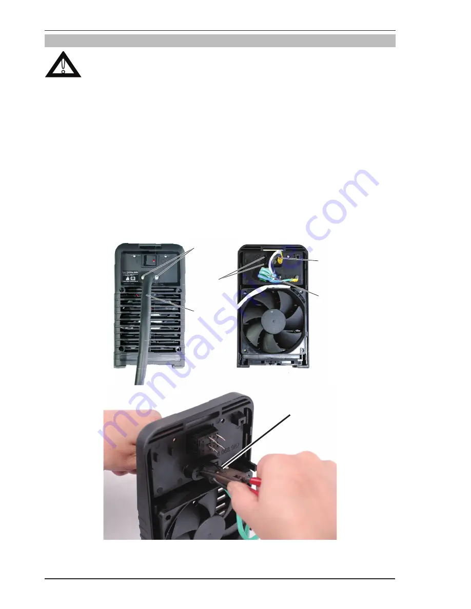
7.06 Power Switch S1 and Power Cord Removal
!
Read and follow safety information in Section 6.02 before proceeding with disassembly
1. Input Power Cord connection s to SW1.
Remove the stab-on wire connections from SW1.
2. SW1 locking tabs
Squeeze the locking tabs and push SW1 out from the rear panel.
3. Input Power Cord.
4. Strain relief screws
Remove the two (2) screws from the strain relief.
5. Input Power Cord ground wire filter.
Cut the tie-wrap and remove the magnet from the ground wire.
6. Pull the Input Power Cord out. It may be necessary to use a flat blade screw driver against the strain relief
tabs, prying outward (Internal side if strain relief) to help remove the cord.
4
3
2
1
5
Art # A-09874
Art # A-09877
6
Summary of Contents for TIG 160S
Page 6: ...This Page Intentionally Blank ...
Page 18: ...FIREPOWER 160 S INTRODUCTION Introduction 2 2 Manual 0 5371 Notes ...
Page 30: ...FIREPOWER 160 S SAFETY AND INSTALLATION Safety and Installation 3 12 Manual 0 5371 Notes ...
Page 40: ...FIREPOWER 160 S THEORY OF OPERATION Theory of Operation 5 2 Manual 0 5371 Notes ...
Page 54: ...FIREPOWER 160 S TROUBLESHOOTING Troubleshooting 6 14 Manual 0 5371 Notes ...
Page 59: ...DISASSEMBLY PROCEDURE FIREPOWER 160 S Manual 0 5371 7 5 Disassembly Procedure 4 Art A 09866 ...
Page 66: ...FIREPOWER 160 S DISASSEMBLY PROCEDURE Disassembly Procedur 7 12 Manual 0 5371 Notes ...
Page 69: ...ASSEMBLY PROCEDURES FIREPOWER 160 S Manual 0 5371 8 3 Assembly Procedures 8 Art A 09883 ...
Page 74: ...FIREPOWER 160 S ASSEMBLY PROCEDURES Assembly Procedures 8 8 Manual 0 5371 Notes ...
Page 78: ...FIREPOWER 160 S REPLACEMENT PARTS Replacement Parts 9 4 Manual 0 5371 Notes ...
Page 80: ...FIREPOWER 160 S ACCESSORIES Accessories 10 2 Manual 0 5371 Notes ...
Page 83: ......

