Page | 10
-
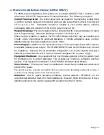
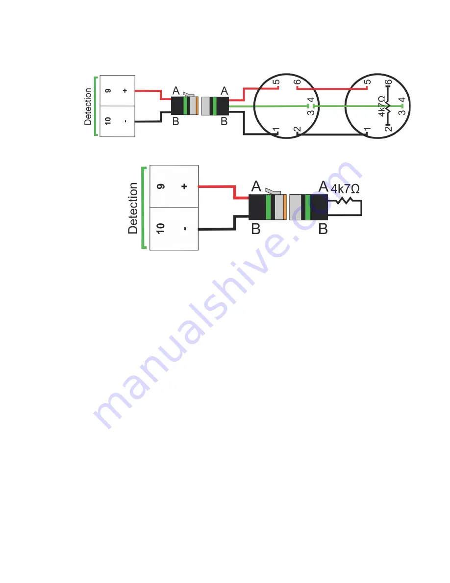
Conventional Detector (Thermal / Smoke):
Conventional Detector
(P/N FP-08920
Thermal / FP-94140 Smoke) can be connected together in quantities up to 30. A 4k7
Ω
End-of-line resistor must be installed in the last detector in the circuit.
-
Detection Not Used:
If detection is not used, the supplied end-of-line plugs (marked
green) must be connected to the Circuit 1 Alarm output.
5.
Circuit 2 Alarm Circuit:
This circuit is
ALARM ONLY
and will only operate the
siren/strobe. Connections for detection and manual call points are the same as Circuit 1
Alarm. If detection is not used, the supplied end-of-line plugs (marked green) must be
connected to the Circuit 2 Alarm output.
6.
Discharge Circuit:
This circuit should remain disconnected until all other circuits are
connected. The control panel
must not
be in an alarm/fault condition when the FirePro
generators are connected, as this may cause an accidental discharge. A Universal Test
Lamp (P/N FP-08800) should be connected to take the control panel out of fault condition
and for any commissioning.
-
Mounting FirePro Generators:
FirePro Generators must be installed using only
approved brackets
with observation of the relevant stream lengths and thermal
clearances
noted in the design calculation and risk assessment. Generators should be
mounted near the top of the risk area, with care taken to aim generators away from
openings or obstacles that may impede dispersion of the suppression agent. Egress
routes for personnel must be kept clear, and not be obstructed by any installed
components or by agent dispersion.


