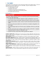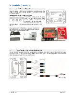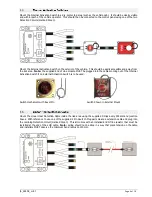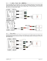
fp_22408_m4.1
Page 6 of 10
The control panel also provides a Shutdown/Warning Relay to shutdown the vehicle's engine and activate any
auxiliary warning equipment (for example sirens or lights).
The colour code for the relay wiring is: Common-Red
Normally Closed-Black
Normally Open-White.
Any device that is wired to the relay must draw its own current from an independent power lead with a 5 Amp AGC
fast blow fuse. One of the supplied 3 Pin Deutsch Plugs is supplied any connection.
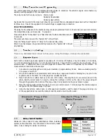
RELAY PROGRAMMING
Press and hold the "Relay Reset" and "Alarm Service" buttons simultaneously for
20 seconds.
The panel will chirp once and the "System OK" LED will flash.
Press the "Relay Reset" button "x" times for the desired relay delay.
After 10 sec has elapsed, the panel will chirp twice and the "System OK" LED will
stop flashing.
There is no dedicated Siren circuit on this panel. Using the Relay a siren can be connected.
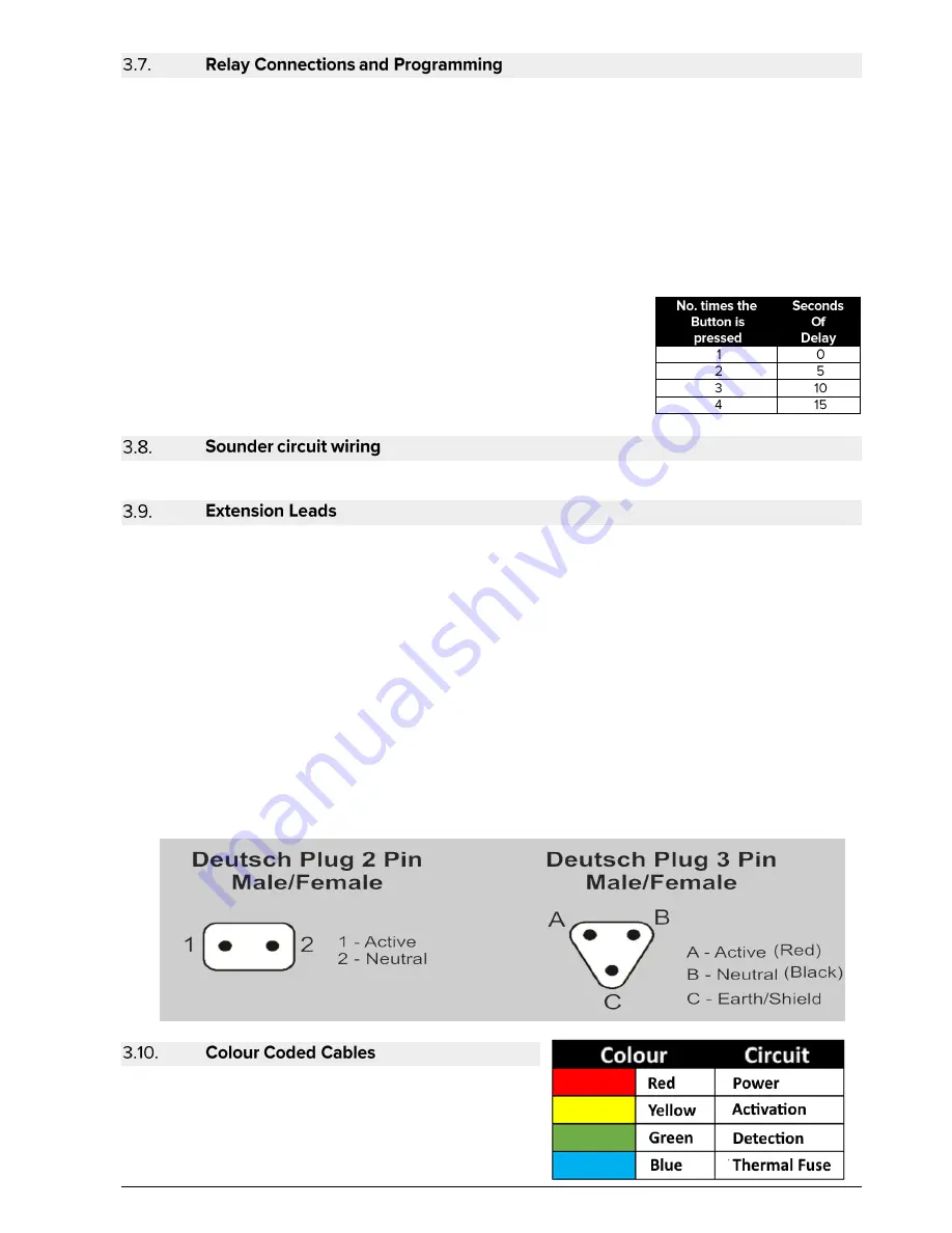
Each FirePro Vehicle Suppression System is supplied with 10 metres of Shielded, 2 hour Fire Rated, 2 Core Cable,
4 x 2 Pin Deutsch Plug Pairs and 3 x 3 Pin Deutsch Plug Pairs. These MUST be used for the construction of any
extension lead. If additional cable or Deutsch plugs are required this needs to be specified by the installer. To
create extension leads follow these steps:
1.
Cut cable to required length and strip outer insulation to approximately 50mm. Remove shielding and for
2 Pin plugs cut earth off.
2.
Strip inner insulation to approximately 6mm and using an approved Deutsch Crimping tool, fix pins to the
exposed ends of the cable. For 3 Pin plugs this includes the earth.
3.
Place heat shrink or rubber boot over the end of the cable. Ensuring that pins are securely fixed to the
cable, identify correct socket on plug by noting the numbers or letter on the side of the plug and push
through the gasket at the bottom of the plug until a click is heard and the pin is locked in place.
4.
Place the locking wedge inside the plug to ensure pins remain secure. For male plugs the locking wedge is
orange and for the female plugs it is green.
5.
Using the heat shrink, rubber boot, or other approved insulation, seal the back of the plug and using one
of the supplied cable ties mark the cable to identify which circuit it will be used.
Cables are colour coded for easy identification. When installing
system, cables should be only connected to the correctly coded
cable. Colour Coding for cables is as follows:
The delay for the activation of the shutdown relay can be programmed from 0 to 15 seconds (in 5 second intervals).
The default time delay is 15 seconds. To program :


