FirePro
®
Technical Manual
Keep this Technical Manual for future use. This
manual lapses when revised. The latest version
is obtainable from FirePro Systems Ltd.
Version 1, 01-07-2010
FirePro
®
products are manufactured by FirePro Systems Ltd
Page 4 of 6
4.3 Trouble
Yellow LED.
•
Off during normal operation
•
Flashes to indicate a fault condition
4.3.1 Fault Indications
•
A beep and a single flash of the Trouble (yellow) LED every 3 seconds – an open
wire in the "Electric Match" input.
•
A beep and two flashes of the Trouble (yellow) LED every 3 seconds – an open
wire or short in the Remote Activation input.
•
A beep and three flashes of the Trouble (yellow) LED every 3 seconds – an open
wire in the Thermistor input.
•
A beep and three flash of the Trouble (yellow) LED every minute – a weak battery.
5
Remote Activation Input
The FPC-1 has a remote activation input that can be used in one of two ways:
•
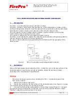
A manual activation switch – remove the End of Line resistor and install it at the
switch as shown in Figure 2.
•
A linear heat detection wire – when connecting a linear heat cable remove the End
of Line resistor and install it at the end of the cable.
6
Open Collector Outputs
The FPC-1 has three open collector outputs that can activate an auxiliary indicating LEDs
or relays. Make sure that the current flow through the open collector does not exceed
the maximum current as specified in the specification section on page 5.
7
What to Do After Activation
Replace the aerosol container and the batteries and verify normal operation (Live LED
flashes every 10 seconds to indicate a normal status).
8
Periodic Maintenance
8.1 Weekly Inspection by the Site's Safety Supervisor
The FPC-1 module should be inspected weekly by the site's safety supervisor for normal
operation:
•
Live LED (green) flashes every 10 seconds
•
Alarm (red) and Trouble (yellow) LEDs are off
•
The buzzer is off
Call your service organisation if any of these conditions are not met.
Summary of Contents for FPC-1
Page 1: ......


