Fire Control Panel
FP-C2
Rev 7.0
Page |
8
8.
Commissioning & Testing
ISOLATE SYSTEM
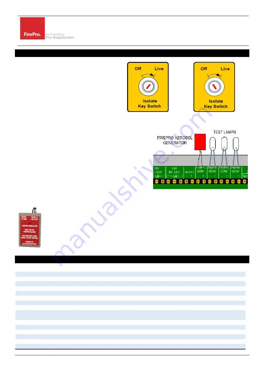
Turn Key-Switch to
“
Off
”
Requires 003 Key
This will create a fault on the Panel.
OPERATIONAL
ISOLATED
TO TEST SYSTEM:
1
Isolate system
–
t urn Key-Switch to
“
Off
”
.
2
Turn Power off.
3
Disconnect FirePro
units and connect test lamps or Test
Modules.
4
Visually inspect each FirePro
unit installed and ensure Bracket
and mounting bolts are secure. The FirePro®
unit must be
clean and free of debris.
5
Inspect all other component detectors, sirens etc. Inspect cable
for any signs of damage.
6
Turn power on to panel and turn to
“
live
”
test detection system
to simulate activation-all test lamps to be lit.
7
Turn off power Isolate system
–
Reconnect all FirePro
units.
8
Turn Power on - Turn system back to Live.
If connecting FP-08800 Test Simulator
–
Then MUST USE V4 of the
test simulator, or the fuse will blow on EACH test.
Note
: If the system has been activated the system activation fuse needs to be inspected as blown fuse
will show as a fault. The Fuse is 1.6AMP Quick Blow.
9.
Specifications
Mains supply
24V DC +10% - 15%
Mains supply fuse
1.6Amp (Quick Blow)
Operating Voltage
19-30V DC
Output voltage
19-30V DC +/- 2%
Standby Current
18mA
Extinguishant release output
19 to 30V DC. Fused at 1.6 Amp
Low Voltage limit
6V DC
–
at this point unit is operational will send fault signal to Sigma XT Panel
Extinguishant release
Immediate
–
Max 4 FirePro Aerosol units
Extinguishant release duration
Latched - Continuous
Detection Type
Hochiki Conventional PE smoke or Thermal Detectors
–
Max of 2 Detectors, can be mixed.
Linear Heat Detection Cable - Latching Type NO
–
LHD Cable Max 30m
Detection Circuit End of Line
6K8 5% ½ Watt resistor
Fault relay contact rating
30VDC 1A Amp max
Fire relay contact rating
30VDC 1A Amp max
Cable Entries
8 x21mm knockouts provided
Terminal capacity
0.5mm
2
to 2.5mm
2
solid or stranded wire
Construction
1.2mm steel
–
Epoxy Powder Coated


