background image

Man-1556 Rev.02 

FPC-2V2 Fire Extinguishant Controller Operation and Installation Manual 

Page 15 of 18 

Step 21 

Power off the unit. 

Step 22 

Turn 

Isolate Key Switch 

to “Off” position. 

Step 23 

Disconnect the test lamps and ensure that the FirePro Generators fitted to 
terminals. 

Step 24 

Place the front frame of the panel. 

Step 25 

Power on the unit. 

Step 26 

Ensure that only the yellow Fault LED on the front panel and the internal 

yellow LED marked LED5 are lit and the buzzer sounds. 

Step 27 

Turn 

Isolate Key Switch 

to live position and ensure that the fault 

indication clears. 

Step 28 

The system recommissioning is completed. 

5.2


Fuse replacement 

Step 1 

Power off the unit. 

Step 2 

Turn 

Isolate Key Switch 

to ”Off” position. 

Step 3 

Remove the front frame of the panel from the back box. 

Step 4 

Flip the front panel frame on the PCB side. 

Step 5 

Locate the fuse holder as indicated in Figure 10. 

Step 6 

Lift the fuse cover and push the fuse to release it. 

Step 7 

Replace the fuse with a 1.6A quick blow fuse. 

Step 8 

Push the fuse in the fuse cover and secure it. 

Step 9 

Push the fuse cover in the fuse holder and secure it. 

Step 10 

Place the front frame of the panel to the back box. 

Step 11 

Power on the unit. 

Step 12 

Turn 

Isolate Key Switch 

to “Live” position 

Summary of Contents for FPC-2V2

Page 1: ...FPC 2V2 Fire Extinguishant Controller Operation and Installation Manual Issue March 2021 Version 1 0 ...

Page 2: ... Generators connection terminals 7 3 4 FIRE contacts for remote signalling 8 3 5 FAULT contacts for remote signalling 8 3 6 Sounder circuit wiring 8 3 7 Connection to addressable modules 9 4 Testing and Commissioning 10 4 1 System Test 12 4 2 Release Test 12 4 3 Detector monitoring Test 12 4 4 Condensed Aerosol Generator monitoring Test 13 5 Testing and Commissioning 14 5 1 System test 14 5 2 Fuse...

Page 3: ...he FPC 2V2 requires a battery backed 24 V DC power supply capable of delivering a minimum of 1 6A for a short period to operate the Condensed Aerosol Generators Terminals are provided for incoming and outgoing connection of the 24 V DC power supply Volt free contacts are available to signal fire and fault conditions to plant or other monitoring equipment By selecting the appropriate jumper link ar...

Page 4: ...erosol into the protected area The internal buzzer will sound and the Fault indicator will illuminate indicating that the Condensed Aerosol Generators have fired and need replacing The internal fire volt free contact will operate and signal any external equipment that is connected to the controller The buzzer may be silenced by pressing the Buzzer Silence button Operating the Isolate key switch by...

Page 5: ...d be mounted with screws of a minimum 4mm diameter in all four fixing positions Figure 1 Fixing centres of mounting enclosure Not to Scale The back box has several 20mm knockouts in the top and bottom Remove the knockouts required and fit 20mm cable glands and the required cables Figure 2 Knockouts Not to Scale If additional cable entries or cable entries in different positions to those provided a...

Page 6: ...imum cable size of 2 5mm2 and a maximum cable length of 160 metres Figure 3 Connection of 24V power supply 3 2 Detection terminals These terminals are for the connection of a conventional type 24V smoke detector or other another detection device such as linear heat detection cable see figures 4 and 5 A 6K8 end of line monitoring resistor is fitted to these terminals This must be removed and place ...

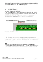
Page 7: ...minals These terminals FIREPRO GEN1 to FIREPRO GEN4 are for the connection of FirePro Condensed Aerosol Generators Test lamps are provided in the terminals to allow testing of the system before connecting the FirePro Condensed Aerosol Generators These test lamps should be removed from the terminals if a FirePro Condensed Aerosol Generator is to be fitted Any FirePro generator outputs that are not ...

Page 8: ...T contacts for remote signalling Volt free changeover contact that will operate whenever there is a fault condition This contact is rated for a maximum of 30V DC and 1 Amp These ratings must not be exceeded 3 6 Sounder circuit wiring There is no dedicated Siren circuit on this FPC 2V2 panel however a siren can be connected to the fire relay output The FIRE terminal on the FPC 2V2 panel is a relay ...

Page 9: ...V2 panel compatible with an addressable input module move jumpers J1 and J2 from their default positions position A to position B The FIRE NO and C terminals can now be connected directly to the addressable input module as shown in Figure 8 Alarm and Fault conditions will be indicated on a suitable address fire alarm control panel Note The volt free contacts cannot be used for anything else when t...

Page 10: ...l ensure that the test lamps that are supplied with the unit are fitted to terminals FirePro GEN1 FirePro GEN2 FirePro GEN3 and FirePro GEN4 When power is applied and all connections are correct only the green Power On LED should be lit If any fault indicators are lit the wiring to the appropriate input or output should be checked and all faults have been cleared before proceeding Figure 9 Unit fr...

Page 11: ...Extinguishant Controller Operation and Installation Manual Page 11 of 18 Figure 10 Connections to FirePro Gen outputs to test system Figure 11 Isolate Key Switch Off and Live Off Live Isolate Key Switch Off Live Isolate Key Switch ...

Page 12: ...e position Step 8 Trigger the detection input by operating a smoke detector or linear heat detector Step 9 Ensure both jumper links J1 J2 are fitted in position A Step 10 Inspect all system components Detectors Sirens etc and all cables for signs of damage 4 3 Detector monitoring Test Step 11 Disconnect the wiring to the detector and ensure that the yellow Fault LED on the front panel and the inte...

Page 13: ...marked LED5 are lit and the buzzer sounds Step 15 Press the Silence Buzzer button and ensure the buzzer silences Step 16 Re connect the test lamp and ensure that the fault indications clear Step 17 Turn the Isolate Key Switch to the Off position and ensure the that the yellow fault LED on the front panel and the internal yellow LED marked LED5 are lit and the buzzer sounds Step 18 Turn the Isolate...

Page 14: ... and the buzzer sounds Step 12 Press the Silence Buzzer button to silence the buzzer and then the Reset button to reset the system Step 13 Disconnect the wiring to the detector and ensure that the yellow Fault LED on the front panel and the internal yellow LED marked LED4 are lit and the buzzer sounds Step 14 Press the Silence Buzzer button and ensure the buzzer silences Step 15 Re connect the det...

Page 15: ...sition and ensure that the fault indication clears Step 28 The system recommissioning is completed 5 2 Fuse replacement Step 1 Power off the unit Step 2 Turn Isolate Key Switch to Off position Step 3 Remove the front frame of the panel from the back box Step 4 Flip the front panel frame on the PCB side Step 5 Locate the fuse holder as indicated in Figure 10 Step 6 Lift the fuse cover and push the ...

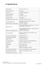
Page 16: ... Smoke or Heat Detectors Max of 2 Detectors can be mixed Linear Heat Detection Cable Latching Type NO LHD Cable Max 30m Detection Circuit End of Line 6K8 5 Watt resistor Fault monitoring Detection and actuator circuits open circuit monitored only Fault relay contact rating 30VDC 1A Amp max Fire relay contact rating 30VDC 1A Amp max Cable entries 8 X 21mm knockouts Terminal capacity 0 52mm to 2 52m...

Page 17: ...7 Indicative system diagram Figure 12 Example of connection to addressable fire alarm panel Man 1556 Rev 02 FPC 2V2 Fire Extinguishant Controller Operation and Installation Manual Page 17 of 18 ...

Page 18: ...d its related documentation designs or drawings adherence e g design documentation construction as built drawings circuit diagram cable lengths and voltage drop calculations etc to local national and international laws and regulations falls entirely within the scope of the contractor consultant assigned for the installation and commissioning In no event regardless of cause shall FirePro Systems be...

Page 19: ...FirePro Systems Ltd 8 Faleas Street CY 4101 Limassol Cyprus EU Tel 357 25 379999 Fax 357 25 354432 Email mail firepro com www firepro com ...

Reviews: