background image

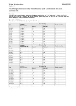
FPC-5V2 

April 2019  


7 | 

P a g e


FPC-5V2


Terminals 


Description 


I/P terminal 

J7 

Linear Heat Detector cable max 10m length 

I/P terminal 

J7 

Linear Heat Detector cable max 10m length 

O/P terminal 

J6 

Condensed Aerosol Generator 1 

O/P terminal 

J6 

Condensed Aerosol Generator 1 

Battery 


3Vdc Lithium battery (CR2 (3V)) 

I/P Rating 


IP30 

Enclosure Heat 

Resistance 


Withstands for a short period heat of up to 180

o

degrees 


Table1: Specifications


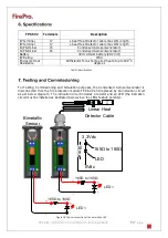
For Testing, Commissioning and Simulation purposes,  the Condensed Aerosol Generator is 
disconnected from the fire protection module FPC-5V2 and replaced by an indication circuit 
as per below diagram.   The indication  circuit includes  a resistor and an  LED  (the indication 
circuit must be installed as illustrated below since the LEDs feature polarity). 

LED 1

165

Ω to 180Ω

3.3Vdc

LED

165

Ω to 180Ω

1

8

 m

a

0Vdc

Bimetallic 

Sensor

Linear Heat 

Detector Cable

+

-

+

-

LED 1

165

Ω to 180Ω

+

-

+

-


Figure 16: Typical connection of the simulation LED  

Summary of Contents for FPC-5V2

Page 1: ...FPC 1 P a g e Operation and User Manual FPC 5V2 Panel Fire Protection Controller Issue April 2019 Version 2...

Page 2: ...2 3 Technical Features 2 4 Assembly of unit 4 5 Installation guidelines 6 6 Specifications 7 7 Testing and Commissioning 7 8 FPC5 V2 Module Assembly 9 9 Adaptor plate junction box coupling required 9...

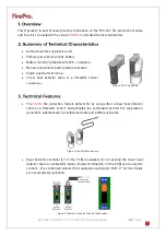
Page 3: ...nections Figure 1 FPC 5V2 module The FirePro fire protection module detects fire by using either a linear heat detector cable or a bimetallic sensor and activates the condensed aerosol fire suppressio...

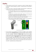
Page 4: ...erosol generator and it is necessary to replace the battery immediately o When no LED is illuminated either the battery is installed in reverse polarity or it is fully discharged or the unit is set in...

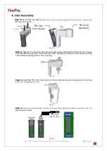
Page 5: ...d Aerosol Generator wires through the FPC 5V2 main body It is important to pass the Condensed Aerosol Generator wires from the same opening of the adaptor plate junction box coupling Figure 6 Step 3 I...

Page 6: ...f the condensed aerosol generator when connected Address this issue first and then proceed to the next step Figure 10 Step 7 Connect the Condensed Aerosol Generator wires electronic PCB Figure 11 Step...

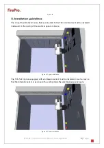
Page 7: ...be installed inside and on the ceiling of the electrical panel enclosure Figure 14 Typical installation The FPC 5V2 module equipped with a bimetallic sensor must be installed in such a way so that the...

Page 8: ...period heat of up to 180o C degrees Table1 Specifications For Testing Commissioning and Simulation purposes the Condensed Aerosol Generator is disconnected from the fire protection module FPC 5V2 and...

Page 9: ...Once the detection line is activated observe whether the LED illuminates Step 6 Cancel the short circuit on the detection line LHD cable or wait for the bimetallic sensor to cool down Step 7 Observe w...

Page 10: ...lectronic PCB CR2 Battery Figure 18 Adaptor plate applicable to Condensed Aerosol Generator series FP 20 Adaptor plate applicable to Condensed Aerosol Generator series FP 40 FP 80 Junction box couplin...

Page 11: ...l 2019 10 P a g e Figure 19 For Box type Condensed Aerosol Generators FP 1200 2000 3000 4200 5700 FP 20 FP 40 80 FP 100 200 500 Figure 19 For Cylindrical type Condensed Aerosol Generators FP 20 40 80...

Page 12: ...FPC 5V2 April 2019 11 P a g e Declarations...

Page 13: ...stbus 70 2288 AB Rijswijk Tel 31 88 998 44 00 www kiwa nl Executed by Kiwa NCP info ncp kiwa nl www kiwafss nl Company FirePro Systems Ltd 8 Faleas Street Agios Athanasios Industrial Area Cy 4041 Lima...

Page 14: ...FP20 T Cylinder No Yes 1 FP20 TH Cylinder Yes No 1 FP40 S Cylinder No Yes 2 FP40 T Cylinder Yes Yes 1 FP80 S Cylinder No Yes 2 FP80 T Cylinder Yes Yes 1 FP100 S Cylinder Yes Yes 1 FP200 S Cylinder Yes...

Page 15: ...s of the supplier manufacturer CEN TR 15276 2 and or evaluation guideline BRL K23003 Point of interest during use or limitation of use The condensed aerosol extinguishing components should not be used...

Page 16: ...d in table 5 Reference to the application instructions Certification mark Fire Class A according EN2 Fire Class B according EN2 Non erasable and non detachable Non flammable Permanent an legible Recom...

Page 17: ...Thermal Activator See 5 12 2 5 12 3 and 7 15 See Kiwa declaration K90415 and K97969 4 4 4 Other methods of ignition device N A 5 Condensed aerosol generator requirements 5 12 Ignition device 5 12 2 E...

Page 18: ...n device Bulb Thermal Activator The bi metal switch and heat cable are mandatory equipped with the FPC 5 ignition device Bi metal switch is tested including an extension cable for bi metal element wit...

Page 19: ...adherence e g design documentation construction as built drawings circuit diagram cable lengths and voltage drop calculations etc to local national and international laws and regulations falls entire...

Page 20: ...FPC 1 P a g e FirePro Systems 8 Faleas Street Agios Athanasios Industrial Area CY 4101 Limassol Cyprus EU Tel 357 25 379999 Fax 357 25 354432 Email mail firepro com www firepro com...

Reviews: