FPC-5V2
April 2019
8 |
P a g e
Step 1:
Remove any power source connected to the system (CR2 Battery).
Step 2:
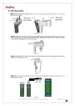
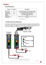
Connect the simulation LED circuit as described in figure 16.
Step 3:
Apply the power source to the system (CR2 Battery).
Step 4:
Create a short-circuit by using the two end-wires of the LHD cable (Linear Heat
Detector cable) or apply heat to the bimetallic sensor.
Step 5:
Once the detection line is activated observe whether the LED illuminates.
Step 6:
Cancel the short-circuit on the detection line (LHD cable) or wait for the bimetallic
sensor to cool down.
Step 7:
Observe whether the LED is off.
Step 8:
If no problem has been observed, remove the power source connected to the
system (CR2 Battery).
Step 9:
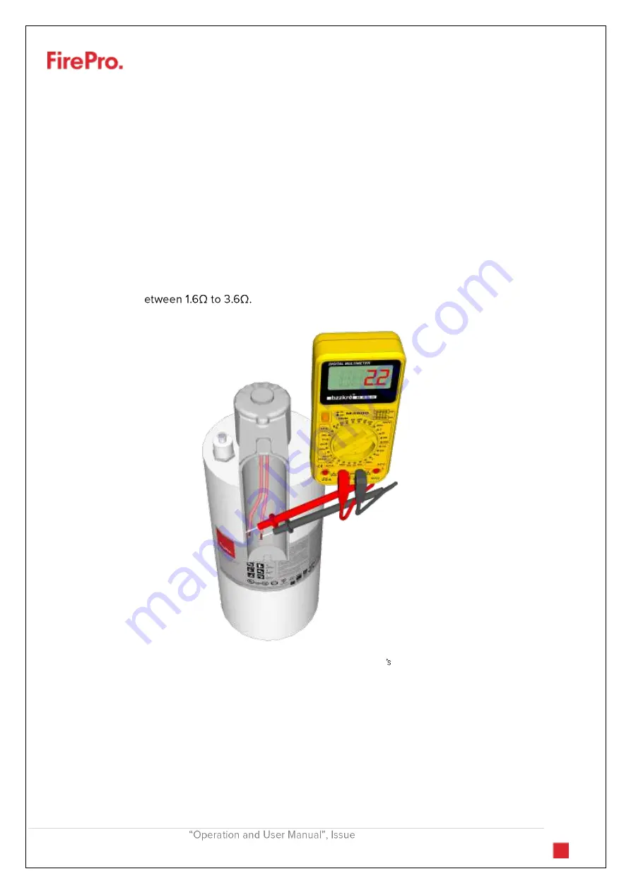
By using an ohm-meter ensure that the ohmic resistance of the condensed aerosol
generators is b
Step 10:
Replace the simulation LED circuit with the condensed aerosol generators.
Figure 17: Measuring the Condensed Aerosol Generator resistance


