Sigma_XT_signs_m3.5.docx
Page 9 of 14
Processor and Watchdog Reset Switches
The status unit is controlled by a microprocessor, which will re-start
itself and continue to run if it stops for any reason such as severe
electrical interference such as an electrical storm.
To ensure that the unit is not being subjected to continual, undue
interference which may affect its proper operation, a CPU fault
indicator is latched on and a fault condition signalled to the control
panel.
If a processor re-start has occurred this latched fault condition will
need to be reset by pressing the WDOG RESET button on the bottom
of the PCB.
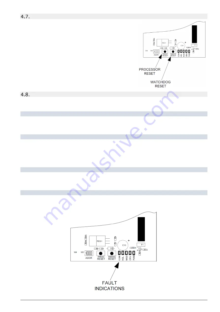
A switch is also provided to manually re-start the processor PROC
RESET. This switch can be used while the status units are connected
to the system to ensure that the unit starts up and establishes
communication with the panel in a controlled and expected manner.
Internal fault indications
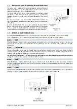
An extinguishant fault indication at the control panel may mean that there are faults at one or more status
units. The status unit fault indications are located along the bottom of the PCB and are as follows:
4.8.1.
COM
This LED indicates that the data communications connection to the control panel is not present. This may be
because the data lines are connected with reverse polarity or are not connected. Check RS485 IN and OUT
connections.
4.8.2.
LOCK OFF
This LED indicates that the Lock Off input is open or short circuit. Check that the correct end of line resistor is
connected to the Lock Off terminals or at the end of the wires connected to the Lock Off terminals and that the
Lock Off input is not short circuited, or the wiring open circuited.
IMPORTANT NOTE: When there is a fault on the Lock Off input then the Lock Off function is invoked which means that the
extinguishant release will not operate until this condition is cleared.
4.8.3.
MOD
This LED indicates that the MODE input is open or short circuit. Check that the correct end of line resistor is
connected to the MODE terminals or at the end of the wires connected to the MODE input and that the MODE input
is not short circuited.
4.8.4.
FUSE
This LED indicates that the electronic fuse has operated. Under this condition, the status unit is not operational.
This may be due to incorrect polarity of the power connection or a failure on the unit itself.


