Sigma_XT_signs_m3.5.docx
Page 8 of 14
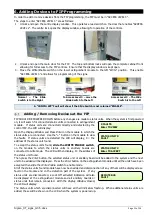
Connection to Hold and Mode inputs
Status units have monitored inputs to which remote Hold or Mode select switches can be connected. These inputs
are monitored for open and short circuit faults and therefore need to have a 470R 1W trigger resistor connected in
series with the activating, normally open switches and 6K8 0.5W end of line monitoring resistors connected across
the end of the cables.
The 6K8 end-of-line monitoring resistors are supplied fitted to the Hold and Mode input terminals and the 470R
trigger resistors are supplied in the accessory bag with the status unit. If either of these inputs are not being used
then the end of line monitoring resistors should be left in the Hold and/or Mode terminals.
Mode input
The mode input is provided to allow connection of remote mode switch or to connect to door interlock contacts.
The system is designed such that any Manual only mode input on the system that is active (input operated by 470R
trigger resistor) will put the system into Manual only mode regardless of the status of any other Mode inputs.
Therefore, for the system to be in Automatic and manual mode, all Mode inputs must be inactive.
Indication of the Mode is given on the front of the status unit by the Manual only or Automatic and manual LEDs.
Hold input
When active (input operated by a 470R trigger resistor) the Hold input allows the extinguishant release countdown
timer to be reset to its maximum time. When the input is de-activated the countdown to extinguishant release will
re-start at the maximum time that is configured at the panel (0 to 60 seconds).
IMPORTANT NOTE: When there is a fault on the HOLD input then the HOLD function is invoked which
means that the extinguishant release will not operate until this condition is cleared.
Mode select keyswitch
Some models of the status units have a mode select switch. The operation of the Mode select switch is as per the
Mode input above.
Manual release
Where fitted, a manual release button replicates the action of the manual release control at the main control panel
and once activated will start the extinguishant release sequence.
A plastic seal is provided in the accessory pack and should be fitted to the manual release flap with a piece of thin
wire to provide an indication if the manual release has been tampered with.
3 Processor and watchdog reset switches


