background image

SYSTEM COMPONENTS 

(cont.)

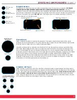
Height Sensors

The height sensor connections must go to their corresponding corners for proper sensor operation. 

THE HEIGHT

SENSORS AND THE WIRE HARNESS CONNECTIONS ARE LOCATION AND POSITION SENSITIVE

. The sensor

connectors are laid out so they work with the sensors mounted on the outside of the frame rail, with the arms pointed
toward the rear of the vehicle. If the height sensors are mounted inside of the frame rail, the arms must point toward
the front of the vehicle. The system 

WILL NOT

work if the height sensors are mounted incorrectly or if the wire

harness connector is in the wrong corner.

Compressor

Select a convenient location for mounting the compressor. This location should provide ample air flow and be
protected from most airborne debris. The surface should be rigid to support the unit. Some examples might include
under the hood on a fender well, or in a vented storage compartment.

Using the compressor feet as a template, mark the three 3/16” holes. Remove the compressor and drill the three
3/16” holes. Before drilling the holes make sure all electrical, brake and fuel lines are cleared from the path of the
drill. It is recommended that burrs be removed from the holes so as not to damage the rubber isolator. Mount the
compressor using the 10-32 machine screws, 10-32 nylon lock nuts and 3/16” flat washers located in your hardware
pack. Proper mounting of this compressor will provide maximum isolation. DO NOT OVER TIGHTEN, further
tightening will crush the insert and isolator and reduce vibration isolation. Secure the ring terminal to a grounded
component of the vehicle’s chassis. Find the red wire on your wire harness marked air compressor.  Connect the
wiring harness to the female spade terminal on the compressor.

3-Gallon Air Tank

Select a location to mount the air tank. This should be a protected location to prevent damage from flying rocks or
debris. Using the holes in the tank brackets as a template, mark the locations of the mounting holes on the mounting
surface. Use a center punch to mark the center of the holes on the mounting surface. 

Before drilling the holes make

sure all electrical, brake and fuel lines are cleared from the path of the drill

. Drill four 3/8” holes on the center

marks. Using the supplied 3/8”-16 x 1” hex bolts and 3/8”-16 nuts and 3/8” washers, attach the air tank to the vehi-
cle. Ensure that a clear access to the fittings on the air tank is maintained.

3

Shown with mounts

and air filter.

1/8 NPT Fitting (1)

3/8”-16 x 1 Hex

Head Bolt (4)

3/8”-16 Flat

Washer (4)

3/8”-16 Flange

Lock Nut (4)

1/4 NPT

Fitting (1)

1/4 NPT
Plug (1)

Air Tank Mounting Hardware

M5 Nylon Lock
Nut (8)

M5 x 8mm
Machine Screw (8)

M6 Nylon Lock
Nut (4)

M6 X 16mm
Machine Screw (4)

Axle Mounting Bracket (4)

Hose Clamp (4)

Height Control Linkage (8)

Height Control Arm (4)

Height Sensor Template (4)

Height Sensor Bracket (4)

Height Sensor (4)

Summary of Contents for 4-corner

Page 1: ......

Page 2: ...Installation or service charges for replacement parts 2 Damage caused by incorrect installation 3 Parts that have been altered or tampered with 4 Damage caused by vehicle accident 5 Damage from misuse...

Page 3: ...at Washer 8 M5 x 8 mm Machine Screw 8 M6 x 16 mm Machine Screw 4 M6 Nylon Lock Nut 4 Height Control Arm 4 Hardware Required for Height Sensor Linkage Installation Refer to Figure 6 Hose Clamp 4 Axle M...

Page 4: ...he Park Wire Connector to ECU to be mounted inside the vehicle Service Switch to be used to turn the system on and off Ignition wire and ground wire Ignition wire should be connected to a source less...

Page 5: ...HEIGHT SENSORS 6 1 4 TUBING 18ft 7 WIRE HARNESS FULL SYSTEM 8 AIR DRYER SYSTEMS 9 BRACKET HEIGHT SENSOR 10 3 8 NPT FITTING 1 4 TUBE 11 1 8 NPT FITTING 1 4 TUBE 12 1 4 NPT FITTING 1 4 TUBE 13 1 4 NPT...

Page 6: ...e mounted under the dashboard and the harness ran through the firewall to corresponding corners valve block and power connections Valve Block The valve block should be placed in a protected location t...

Page 7: ...d 3 16 flat washers located in your hardware pack Proper mounting of this compressor will provide maximum isolation DO NOT OVER TIGHTEN further tightening will crush the insert and isolator and reduce...

Page 8: ...the wire harness Simply pull the switch off the connector to mount it to your vehi cle After mounting the switch to the vehicle reconnect the switch to the wire harness The switch should click into t...

Page 9: ...ion is fully extended to damper limit Then to determine the jounce suspension position that you will need to mount the height sensors just jack the sus pension up to that point into the jounce stop Ma...

Page 10: ...si tion the sensor so that operates within the yellow portion of the sensor installation template For example if you have a 4 link type rear suspension you can simply locate the linkage a bit closer t...

Page 11: ...ow set Slowly move suspension to the opposite end of its travel ensuring that the sensor arm stays within the limits of the template The parts that you will need for the linkage are M5 threaded rod tw...

Page 12: ...eight seconds The top light on the height selection switch should start blinking This will indicate that the highest height needs to be programmed into the ECU STEP 4 Programming Highest Height Set th...

Page 13: ...d Height is designed to be used for show or ease of ingress and egress from the vehicle The vehicle should not be driven in this mode Ride Height is designed to be the primary operating position of th...

Page 14: ...to withstand the most severe vehicular environments The sensor has been used on high mileage and off road applications The tensile load that the arm has withstood approximately 600lbs in an applicatio...

Page 15: ...to the location requiring protection How does the system indicate that the programming portion of the installation is complete in the WR8 760 2230 IntelliRide system In step 5 of programming the vehi...

Page 16: ...sensors to the corresponding corners as indicated on the wire harness On the WR8 760 2230 IntelliRide system the height change up will not work will not level up The current height is displayed on th...

Page 17: ...s locked down no function The system will not level or change height The lights toggle slowly The ground is removed from the valve block Check grounding on valve block wire The WR8 760 2230 system is...

Page 18: ...For the latest technical information and support questions answers please visit www fsip com ir 14...

Page 19: ...TECHNICAL 15...

Page 20: ...Firestone Industrial Products Company 12650 Hamilton Crossing Blvd Carmel IN 46032 5400 www fsip com Intelliride...

Reviews: