background image

www.desatech.com

114745-01D

0

INSPECTING bURNERS

Continued

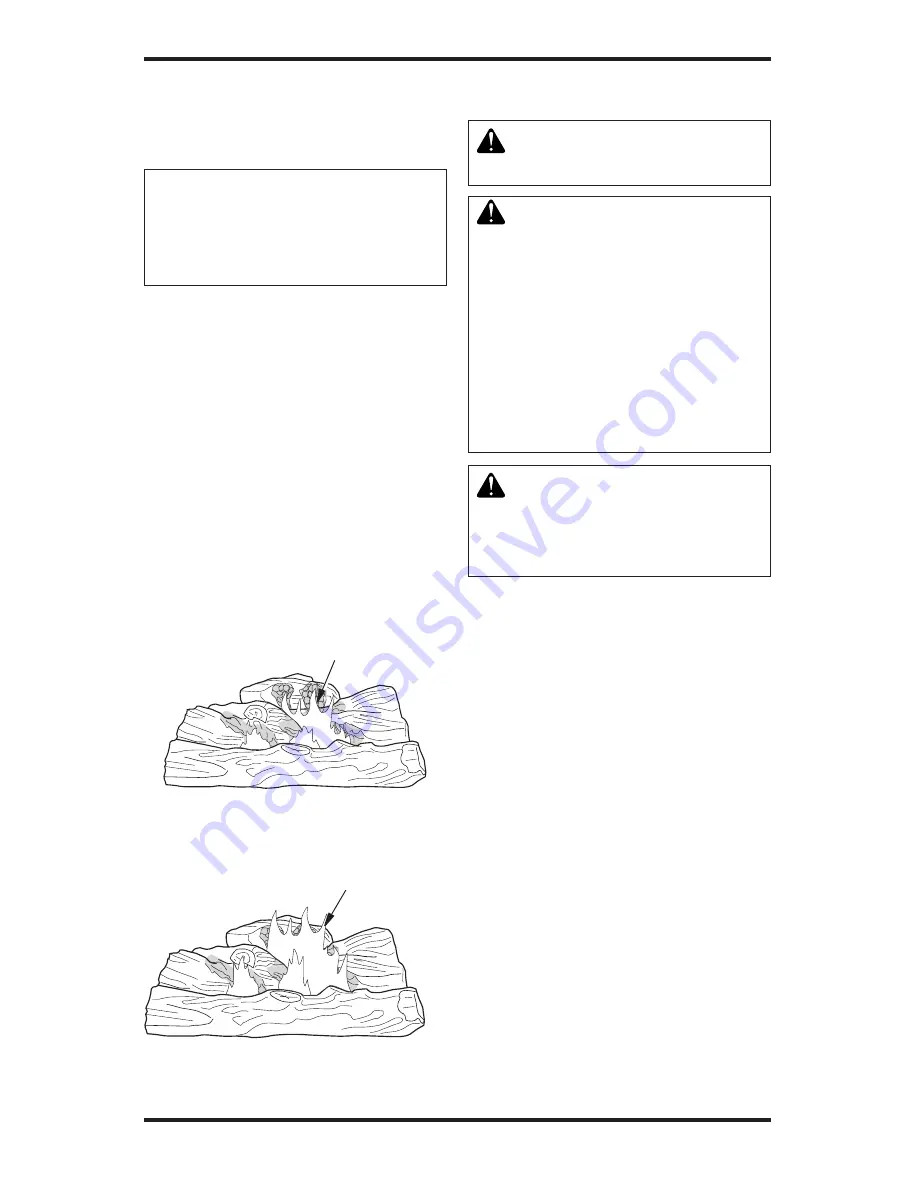
BURNER FLAME PATTERN

Figure 24 shows correct burner flame pattern. 

NOTICE: Do not mistake orange 

flames with yellow tipping. Dirt 

or other fine particles are burned 

by heater, causing brief patches 

of orange flame.

If burner flame pattern is incorrect, as shown in 

Figure 25 

•  turn heater off (see 

To Turn Off Gas to Appli-

ance

, page 17)

•  see 

Troubleshooting

, page 22

The flames from the burner travel horizontally 

through the log set and emerge at the middle and 

rear of the set against the back logs.

The flames are blue off the burner and as they 

progress through the log set, change to a light 

yellow color, yellow decorative flames are visible 

as the flames exit the log set. 

The base of the log set and the underside of the 

top logs glow red. Natural gas models will burn 

with more blue flame, while propane gas model 

will burn with bright yellow flame.

Figure 24 - Correct Burner Flame Pattern

Figure 25 - Incorrect Burner Flame 

Pattern 

Blue and Bright
Yellow flames

Darker 
Orange 
Flames 

CLEANING AND 

MAINTENANCE

  WARNING:  Turn  off  heater 

and let cool before cleaning.

  CAUTION:  You  must  keep 

control  areas,  burners  and 

circulating  air  passageways 

of  heater  clean.  Inspect  these 

areas of heater before each use. 

Have  heater  inspected  yearly 

by  a  qualified  service  person. 

Heater may need more frequent 

cleaning  due  to  excessive  lint 

from carpeting, pet hair, bedding 

material, etc.

  WARNING:  Failure  to  keep 

the primary air openings of the 

burner clean may result in soot-

ing and property damage.

BURNER INjECTOR HOLDER AND 
PILOT AIR INLET HOLE

The primary air inlet openings allow the proper 

amount of air to mix with the gas. This provides 

a clean burning flame. Keep these holes clear of 

dust, dirt, lint and pet hair. Clean these air inlet 

openings prior to each heating season. Blocked 

air openings will create soot. We recommend 

that you clean the unit every three months during 

operation and have heater inspected yearly by a 

qualified service person.

We also recommend that you keep the burner 

tube and pilot assembly clean and free of dust and 

dirt. To clean these parts we recommend using 

compressed air no greater than 30 PSI. Your local 

computer store, hardware store or home center 

may carry compressed air in a can. You can use a 

vacuum cleaner in the blow position. If using com

-

pressed air in a can, please follow the directions on 

the can. If you don't follow directions on the can, 

you could damage the pilot assembly.

Summary of Contents for VFRMV18NA

Page 1: ...ectrical switch do not use any phone in your building Immediatelycallyourgassupplierfromaneighbor s phone Follow the gas supplier s instructions If you cannot reach your gas supplier call the fire department Installation and service must be performed by a quali fied installer service agency or the gas supplier INSTALLER Leave this manual with the appliance CONSUMER Retain this manual for future re...

Page 2: ...er WARNING This appli ance is for installation only in a solid fuel burn ing masonry or UL127 factory built fireplace or in a listed ventless firebox enclosure It is design certified for these installations in accor dance withANSI Z21 11 2 Exception Do not install this appliance in a fac tory builtfireplacethatin cludes instructions stat ing it has not been tested or should not be used with unvent...

Page 3: ...Any change to this log set or its controls can be dangerous WARNING Donotuseablow erinsert heatexchangerinsertor otheraccessorynotapprovedfor use with this appliance WARNING This appliance is equipped with natural or pro pane LP gas Field conversion is not permitted SAFETY INFORMATION Continued WARNING Donotallow fans toblowdirectlyintothefireplace Avoidanydraftsthatalterburner flame patterns Ceil...

Page 4: ...ter SAFETY INFORMATION Continued 7 Topreventthecreationofsoot followtheinstruc tions in Cleaning and Maintenance page 20 8 Before using furniture polish wax carpet cleaner or similar products turn heater off If heated the vapors from these products may create a white powder residue within the burner box or on adjacent walls and furniture 9 This heater needs fresh outside air ventilation to run pro...

Page 5: ...e are four optional remote controls that can be purchased separately Wall switch Hand held ON OFF remote Wall thermostat Hand held thermostat remote See Accessories page 26 Thewallthermostatorhand heldthermostatmaynot be used where vented decorative listings is required Product Features OPERATION This heater is clean burning It requires no outside venting There is no heat loss out a vent or up a c...

Page 6: ...ovide additional fresh air Unusually tight construction is defined as construction where a Walls and ceilings exposed to the out side atmosphere have a continuous water vapor retarder with a rating of one perm 6 x 10 11 kg per pa sec m2 or less with openings gasketed or sealed and b weather stripping has been added on openable windows and doors and c caulking or sealants are applied to areas such ...

Page 7: ...ION Continued The space in the previous example is a confined space because the actual Btu Hr used is more than the maximum Btu Hr the space can support You must provide additional fresh air Your options are as follows A Rework worksheet adding the space of an adjoining room If the extra space provides an unconfined space remove door to adjoining room or add ventilation grills between rooms See Ve...

Page 8: ...tion Grills Into Adjoining Room Option 2 Ventilation Grills Into Adjoining Room Option 1 12 12 Installation NOTICE This heater is intended for use as supplemental heat Use this heater along with your primary heating system Do not installthisheaterasyourprimary heating source If you have a central heating system you may run system s circulating blower while using heater This will help circulatetheh...

Page 9: ...e LP for your unit If your gas supply is not correct do not install in fireplace Call dealer where you bought the appliance for proper type of appliance Installation Continued WARNING This appliance is equipped for natural or pro pane LP gas Field conversion is not permitted INSTALLATION AND CLEARANCES for vent free operation WARNING Maintain the minimum clearances If you can provide greater clear...

Page 10: ...Figure 5 Heat Resistant Material Slate Marble Tile etc Above Fireplace Noncombustible Requirements for Material Distance A Safe Installation 12 or more N o n c o m b u s t i b l e material OK Between 8 and 12 24 Models Install fireplace hood accessory GA6050 GA6052 GA6053 see Accessories page 26 18 Model Noncom bustible material OK Less than 8 Noncombustible material must be extended to at least 8...

Page 11: ...nimum Non Combustible Material 8 Min 14 1 2 18 5 8 22 1 2 All minimum distances are in inches 26 2 1 2 6 8 10 12 Distances to Underside of Mantel Hood GA6050 GA6052 or GA6053 Top of Fireplace Opening Underside of Mantel Shelf NOTICE Surface temperatures ofadjacentwallsandmantelsbe comehotduringoperation Walls and mantels above the firebox may become hot to the touch If installed properly these tem...

Page 12: ...ill keep damper open Installation instructions are included with clamp accessory Figure 10 Attaching Damper Clamp Damper Damper Clamp Damper Manufactured Fireplace Masonry Fireplace Damper Clamp Damper See chart below for minimum permanent flue opening you must provide Attach damper clamp so the minimum permanent flue opening will be maintained at all times Area of Various Standard Round Flues Dia...

Page 13: ...ion Items Needed Before installing heater make sure you have the items listed below external regulator supplied by installer piping check local codes sealant resistant to propane LP gas equipment shutoff valve test gauge connection sediment trap tee joint pipe wrench approved flexible gas line with gas connector if allowed by local codes provided ACSAdesign certified equipment shutoff valve with 1...

Page 14: ... going into heater controls If sediment trap is not installed or is installed wrong heater may not run properly Installation Continued CAUTION Avoid damage to gas control Hold gas control with wrench when connecting it to gas piping and or fittings CHECKING GAS CONNECTIONS WARNING Testallgaspiping and connections for leaks after installing or servicing Correct all leaks at once WARNING Never use a...

Page 15: ...gas or opening main gas valve located on or near gas meter for natural gas or using compressed air 3 Check all joints from gas meter to equipment shutoff valve for natural gas or propane LP supply to equipment shutoff valve for propane LP see Figure 15 or 16 Apply noncorrosive leak detection fluid to all joints Bubbles form ing show a leak 4 Correct all leaks at once Installation Continued Figure ...

Page 16: ...spect the appliance and to replace any part of the control system and any gas control which has been under water LIGHTING INSTRUCTIONS WARNING If fireplace has glass doors never operate this heater with glass doors closed If you op erateheaterwithdoorsclosed heat buildup inside fireplace will cause glass to burst Also if fireplace opening has vents at the bottom you must open the vents before oper...

Page 17: ...p out when released contact a qualified service person or gas supplier for repairs Note If pilot goes out repeat steps 4 through 8 page 16 OPERATING HEATER Continued Figure 17 Control Knob and Ignitor Button Location Manual Controlled Piezo Ignitor Switch in OFF Position Control Knob Flame Adjustment Knob 9 Slightly push in and turn control knob coun terclockwise to the ON position 10 Wait one min...

Page 18: ... Selector Switch in REMOTE Position Control Knob Flame Adjustment Knob On Off Series Model HRC100 Hold the control button on the hand held remote until burner turns on Hold the con trol button again until burner turns off see Figure 20 To Lock press both buttons on hand held remote control until light stops flashing Hand held remote control is now locked If the fire is on it will be turned off aut...

Page 19: ... feature allows the user to lock unlock the keypad on the hand held remote in the MANU or AUTO mode to prevent inadvertent operation i e children operating the hand held remote control etc The keypad is locked in either on or off Press the POWER and LOCK buttons together to turn the unit on or off Inspecting Burners Check pilot flame pattern and burner flame pat terns often PILOT FLAME PATTERN Fig...

Page 20: ...t keep control areas burners and circulating air passageways of heater clean Inspect these areas of heater before each use Have heater inspected yearly by a qualified service person Heater may need more frequent cleaning due to excessive lint fromcarpeting pethair bedding material etc WARNING Failure to keep the primary air openings of the burner clean may result in soot ing and property damage Bu...

Page 21: ...urner repeat steps 3 and 4 Clean the pilot assembly also A yellow tip on the pilot flame indicates dust and dirt in the pilot assembly There is a small pilot air inlet hole about 2 from where the pilot flame comes out of the pilot assembly see Figure 27 With the unit off lightly blow air through the air inlet hole in the same direction as gas flow You may blow through a drinking straw if compresse...

Page 22: ...ne LP only 6 ODS pilot is clogged 7 Gas regulator setting is not correct REMEDY 1 Reconnect ignitor cable 2 Free ignitor cable if pinched by any metal or tubing Keep ignitor cable dry 3 Tighten nut holding piezo ig nitortobasepaneloflogset Nut is located behind base panel 4 Replace ignitor cable 5 Replace piezo ignitor 6 Replace pilot assembly for remote ready units Replace ignitor electrode for v...

Page 23: ...knob pressed in 30 seconds 3 Wait one minute for safety in terlock system to reset Repeat ignition operation 4 Fully open equipment shutoff valve 5 A Contact local natural or propane LP gas company B Clean ODS pilot see Cleaning and Maintenance page 20 or replace ODS pilot assembly 6 Hand tighten until snug then tighten 1 4 turn more 7 Replace pilot assembly 8 Replace control valve 1 Contact local...

Page 24: ...on and let warm up for a minute 2 Operate burners until air is removed from line Have gas line checked by local natural or propane LP gas company 3 Observe minimum instal lation clearances see pages 9 through 12 4 Clean burners see Cleaning and Maintenance page 20 or replace burner orifice s 1 Turn heater off when using furniture polish wax carpet cleaners or similar products 1 Refer to Air for Co...

Page 25: ...clogged 1 Gas leak See Warning statement at top of page 2 Control valve or gas control defective 1 Foreign matter between control valve and burner 2 Gas leak See Warning statement at top of page 1 Hand held remote control is too close to heater REMEDY 1 Open window to ventilate room Stop using odor caus ing products while heater is running 2 Refill supply tank propane LP only 3 Locateandcorrectall...

Page 26: ...as purchase date Usually we will ask you to return the part to the factory Parts Not Under Warranty Contact authorized dealers of this product If they can tsupplyoriginalreplacementpart s callDESA at 1 866 672 6040 for referral information When calling DESA have ready model and serial numbers of your heater the replacement part number Service Hints When Gas Pressure Is Too Low pilot will not stay ...

Page 27: ...culating smooth face models are ideal for custom trim applications such as stone or marble FB32C CIRCULATING FB32NC NON CIRCULATING SERIES Not Shown For all models ACCESSORIES Continued FB36CA FB42C SERIES CIRCULATING FB36NCA FB42NC SERIES NON CIRCULATING Not Shown For all models DAMPER CLAMP GA6080 Not Shown For all models Permanently opens chimney flue damper for vented operation LAVA ROCK GA606...

Page 28: ...www desatech com 114745 01D 28 Illustrated Parts Breakdown VFRMV18NA VFRMV18PA VFRMV24NA Shown VFRMV24PA 1 2 3 4 6 7 8 9 10 11 12 13 14 15 16 17 18 19 20 21 22 23 24 24 24 24 24 24 24 5 25 26 27 ...

Page 29: ...1 114793 01 114793 01 114793 01 Piezo Switch Bracket 1 14 097159 04 097159 04 097159 04 097159 04 Piezo 1 15 14579 14579 14579 14579 Rocker Switch 1 16 111817 01 111817 01 111817 01 111817 01 Main Gas Line 1 17 114804 01 114804 01 114804 01 114804 01 ODS Pilot Line 1 18 103784 01 103784 01 103784 01 103784 01 ON PILOT OFF Knob Extension 1 19 103784 02 103784 02 103784 02 103784 02 HI LO Knob Exten...

Page 30: ...______________________________ ______________________________________________________ ______________________________________________________ ______________________________________________________ ______________________________________________________ ______________________________________________________ ______________________________________________________ _______________________________________...

Page 31: ...______________________________ ______________________________________________________ ______________________________________________________ ______________________________________________________ ______________________________________________________ ______________________________________________________ ______________________________________________________ _______________________________________...

Page 32: ...ter MUST be installed by a qualified installer in accordance with all local codes and instructions furnished with the unit This warranty does not apply to parts that are not in original condition because of normal wear and tear or parts that fail or become damaged as a result of misuse accidents lack of proper maintenance or defects caused by improper installation Travel diagnostic cost labor tran...

Reviews: