MAGNET TESTING:
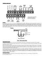
Place the magnet provided with the instruction kit on top of the housing between the raised sections above the detector
head (as indicated on the unit cover). Allow at least five (5) seconds for alarm initiation. Remove magnet and reset detector.
SMOKE TESTING:
Using smoke test canister with testing nozzle (Part Number 565), insert the test gas nozzle into the test point on the unit
cover. Press can against cover to release gas into chamber. CAUTION: Do not spray gas for more than 1/2 second. Overuse of test gas
facility will result in detector contamination.
After 15 to 20 seconds the detector head will go into alarm, illuminating the detector head LED and causing the duct unit functions to operate,
relays will change state and the remote accessories if attached will function. Please allow several minutes for the gas to evaluate the chamber
before the detector may be reset.
If no test gas is available to conduct the testing, remove cover and blow smoke from a cotton wick or punk directly at the head to cause alarm.
The alarm indicator will illuminate within one minute.
Should testing be required for simulated fire conditions, smoke bombs placed in the duct may not be suited for the particular detector head
selected and installed.
Ionization Detector Head 2850-450 utilizes a radioactive source as its means of detection and will detect smoke particles of between .1 and 1
micron in size.
Photoelectric Detector Head 2850-550 operates on the principle of light scatter and will detect smoke particles of between 1 and 10 microns in
size.
When purchasing smoke bombs for functional testing, ensure smoke particle sizes comply with the criteria as described above.
MAINTENANCE
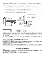
Each installation location must be assessed on its own merits. If the protected area is of a very dirty nature then the Firex Duct units will have
to be checked and cleaned on a Quarterly basis or when cleaning is required.
As a guideline the detector head should be cleaned every six months or as required.
The best methods of cleaning are to vacuum the detector head thoroughly or to blow the detector head out using compressed air.
Do not use chemicals to clean the detector head housing as this could contaminate the detector head and damage the casing.
Sensing tubes must be inspected and cleaned in accordance with the schedule as determined above, to allow the free flow of air through the
sensing tube.
AP 186 MA 2650-760; 01/01
Model Number:
Detector Model Number:
S65 Ionization Detector Head 2850-450
S65 Photoelectric Detector Head 2850-550
POWER REQUIREMENTS
QUIESCENT CURRENT
ALARM CURRENT
24V AC 39.4mA 24V AC 128.7mA
24V DC 13.5mA 24V DC 59.3mA
115V AC 13.8mA 115V AC 27.0mA
230V AC 7.9mA 230V AC 16.0mA
RELAY CONTACT RATINGS:
Alarm contacts: 2 form “C” rated at 10AMPS @ 115V AC resistive, 1 Form A @ 2AMPS
Trouble contacts: 1 Set form “C” rated at 10AMPS @ 115V AC resistive
Air velocity: 300 to 4,000 ft/min
Ambient temperature: Model 2650-760 32
o
F to 1
55
o
F (0
o
C to
6
8
o
C)
:
Model 2650-761 32
o
F to 100
o
F (0
o
C to 38
o
C)
Humidity:
10% to 85% R.H. no condensation
Material:
Gray plastic backbox with clear plastic cover
Dimensions:
L-13 1/2”, X H-4 1/2”, Depth - 2 1/4”
Max. net wt.:
3 lbs.
Radioactive element:
For Firex 2650-760 (Ionization model)
Americium 241, 0.9 micro curie
Do not expose to corrosive atmospheres.
PRODUCT SPECIFICATIONS
2650-760 Ionization
24V AC/DC, 115V AC, 230V AC
2650-761 Photoelectric
24V AC/DC, 115V AC, 230V AC
Maple Chase Company
2820 Thatcher Road
Downers Grove, Illinois 60515 USA
Tel1 630 719 5500 Fac1 630 719 4400
Technical Service Tel1 800 445 8299
E-mail mctechservices@maplechase.com
www.maplechase.com
TM


