11
The scanner should ideally sight a target area of 4 to 25 square inches (25-250cm
2
) of the flame
front. The flame front is a plane within the combustion space separating the region of unburned fuel
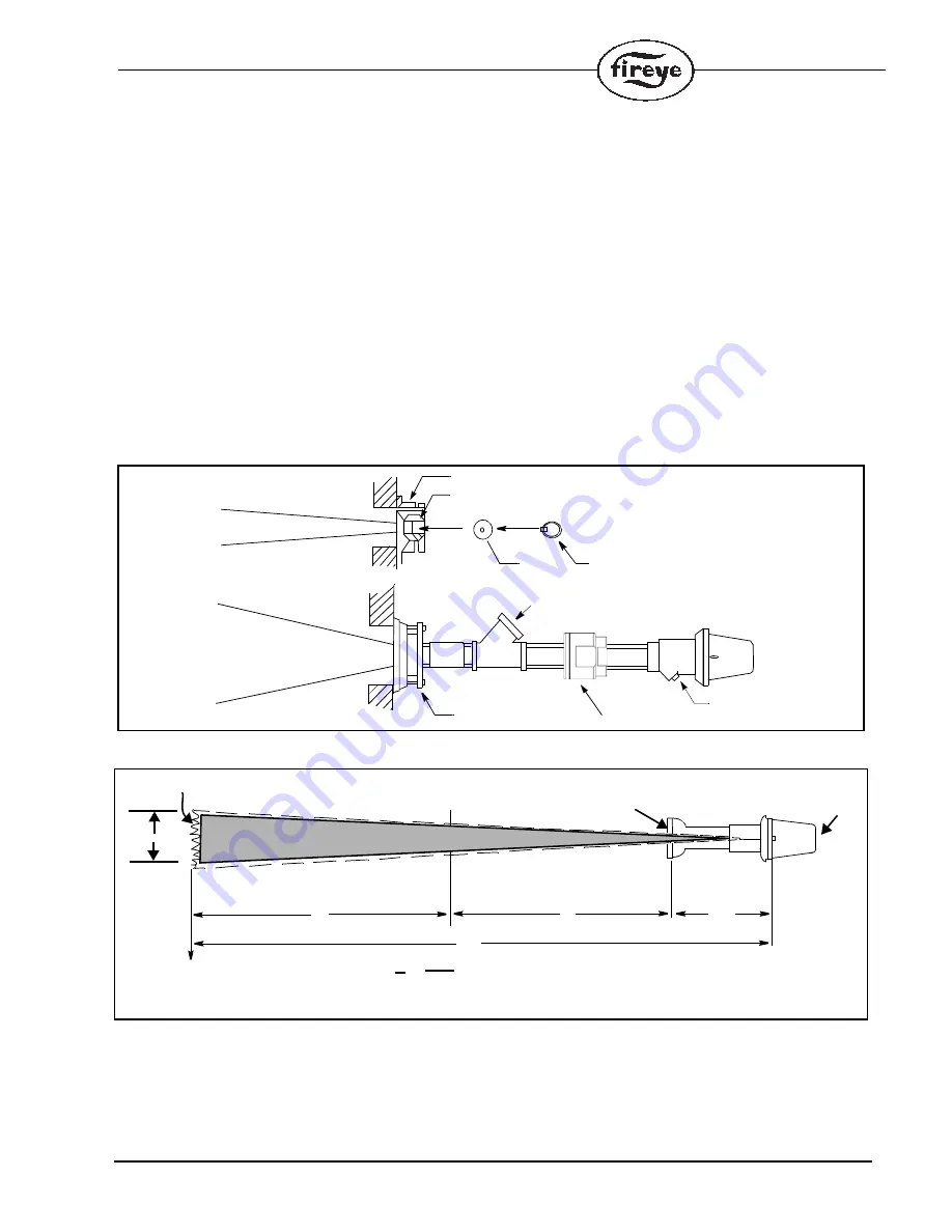
from the burning fuel. For example, if a 1/2 inch diameter orifice is placed within a mounting swivel
one foot from the scanner lens, and the swivel mount is located on the surface of a 4 foot deep wind-
box, and if the range of stable flame is 5 feet beyond the windbox, the flame front target area is 19.6
square inches as shown in figure 16 below.
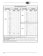
ORIFICES
Figure
Qty.
Part Number
Description
13
1
53-121
Orifice Kit: Contains following items:
13A
1
53-121-2
Orifice: Diameter = 0.062"
13B
1
53-121-3
Orifice: Diameter = 0.078"
13C
1
53-121-4
Orifice: Diameter = 0.093"
13D
1
53-121-5
Orifice: Diameter = 0.109"
13E
1
53-121-6
Orifice: Diameter = 0.125"
13F
1
53-121-7
Orifice: Diameter = 0.187"
13G
1
53-121-8
Orifice: Diameter = 0.250"
13H
1
53-121-9
Orifice: Diameter = 0.375"
13I
1
53-121-10
Orifice: Diameter = 0.500"
13J
2
34-181
Orifice Retainer
FIGURE 15.
ORIFICE LOCATION
FIGURE 16.
SCANNER WITH ORIFICE
Note: There is an inverse relationship between discrimination and sensitivity.
Heat Insulating Nipple
The heat insulating nipple (P/N 35-127-1, -3) is used to prevent heat transfer from the hot sight pipe
to the scanner head.
SWIVEL MOUNT
ORIFICE RETAINER
PURGE
ORIFICE
FIELD OF VIEW
FIELD OF VIEW
BALL
AIR SUPPLY
3/8" PLUG
1" SWIVEL MOUNT
60-1199-1,2 SEALING COUPLING
45UV5
5’
FLAME FRONT
.5" DIA ORIFICE
4’
10’
WINDBOX
X =DIAMETER OF TARGET AREA
x = 10 ft
.5 1 ft
x = 5 inches
TARGET AREA =
¼
(x/2)
2
= 19.6 square inches
X
TARGET
AREA
FIELD OF
VIEW
19.6 SQ.IN.
1’


