© 2020 Carrier
12
9.
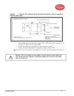
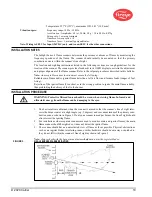
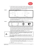
The scanner lens must be kept free of contaminants (oil, ash, soot, dirt) and the scanner housing
temperature must not exceed its maximum rating of 150°F (65°C). Excessive temperatures will
shorten scanner life. Both requirements will be satisfied by a continuous injection of purge air at
either the 3/8” housing inlet or the 1” “Y” connection ahead of the swivel mount as shown in
Figures 6, 7 and 8.
Note: Internal scanner temperature is available via the display. See “Status Menu” under
“Programming the Scanner.”
The scanner mounting may be made with provision for purge air through only the 3/8” opening as
shown in Figure 8 or for purge air through either the 3/8” opening or the 1” “Y” connection as shown
in Figure 6. In the latter arrangements, normally only one of the two connections is provided with
purge air and the other connection is plugged. When a sealing coupling is used as shown in Figure 6,
the 1" “Y” connection is used for the purge air and the 3/8” opening is plugged.
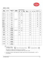
It is good practice to use the sealing coupling (P/N 60-1199-X with NPT or BSP threads) on all
installations to insure against unwanted furnace pressures from damaging the scanner lens.
Under normal conditions, with clean burning fuels and moderate ambient temperature conditions,
purge air flow of approximately 4 SCFM (113 l/min) is generally adequate. Up to 15 SCFM
(425 l/min) may be required for fuels that produce high levels of ash or soot, or for hot environments
to maintain the scanner’s internal temperature within specification.
MECHANICAL ACCESSORIES
Surface Mounting Flange (Required)
Standard:
Cast aluminum
with gray polyester powder coat finish. Contains an integral heat-insulating female
thread insert (external heat-insulating nipple not required).
P/N 60-2919-1 1" NPT female pipe mount with 3/8” NPT female cooling air connection.
P/N 60-2919-2 1" BSP female pipe mount with 3/8” BSP female cooling air connection.
Optional:
Cast aluminum
with grey polyester powder coat finish. Does not contain heat-insulating insert.
P/N 60-2692-4, 1" NPT female pipe mount with 3/8" NPT female cooling air connection.
P/N 60-2693-4, 1" BSP female pipe mount with 3/8" BSP female cooling air connection.
Swivel Mount (Optional)
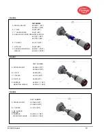
The scanner swivel mount, P/N 60-1664-X (see Figure 9, Item A), is used to adjust the scanner
sighting angle after the scanner has been installed, The swivel mount is shown in Figures 6, 7, 8, and 9.
Sealing Coupling with Quartz Window (Optional)
The sealing coupling, P/N 60-1199-x (see Figure 6, Item D), is used whenever a coupling or a seal is
required for scanner piping. The quartz window blocks furnace pressure, hot gases and soot from
coming in contact with the scanner and contaminating the lens. P/N 60-1199-1 has a 1" NPT thread,
p/n 60-1199-2 has a 1" BSP thread. When the sealing coupling is used, a 1 inch “Y” fitting must be
used downstream of it for connection of a purge air supply (plug 3/8”opening).
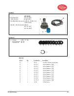
Orifice Kit (Optional)
An orifice may be used to restrict the scanner’s field of view aiding discrimination between the tar-
get flame and other flames in the combustion chamber. An orifice may also be used to reduce the
total amount of radiation reaching the scanner, thereby avoiding the chance of saturation. Orifice kit
(P/N 53-121) contains nine different orifice sizes, and two retaining clips. The orifice can be installed
either within the 60-1664 swivel mount, within the 60-1199 coupling, or within the 60-
2919-1, 60-2919-2 surface mounting flange. Refer to figures 10 and 11.
Cooling Cover/Vortex-Tube Cooler Kit (Optional)
For high ambient temperature applications, a Cooling Cover (p/n 60-2930-x) and Vortex-Tube
Cooler Kit (P/N 60-2720) are available. Refer to bulletins 133-749 and CU-103 for details.
Summary of Contents for InSight 4 Series
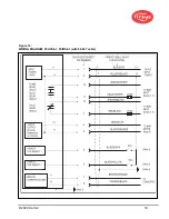
Page 19: ... 2020 Carrier 19 Figure 14 WIRING DIAGRAM 95UVS4 1 95IRS4 1 with 59 547 cable ...
Page 27: ... 2020 Carrier 27 THE MAIN STATUS MENU FIGURE 20 MAIN STATUS MENU LOOP ...
Page 36: ... 2020 Carrier 36 THE CONFIG MENU FIGURE 23 CONFIG MENU LOOP ...
Page 40: ... 2020 Carrier 40 THE AUTO CONFIG MENU FIGURE 25 AUTO CONFIG MENU LOOP ...
Page 43: ... 2020 Carrier 43 THE FILE COPY MENU FIGURE 26 FILE COPY MENU LOOP ...
Page 45: ... 2020 Carrier 45 THE 4 20 mA MENU FIGURE 27 4 20mA MENU LOOP ...
Page 47: ... 2020 Carrier 47 THE DATE TIME MENU FIGURE 28 DATE TIME MENU LOOP ...
Page 49: ... 2020 Carrier 49 THE COMMS MENU FIGURE 29 COMMS MENU ...
Page 51: ... 2020 Carrier 51 THE MANUAL CONFIG MENUS FIGURE 30 ...
Page 52: ... 2020 Carrier 52 MANUAL CONFIG MENUS continued FIGURE 31 ...


